Lockable Gas Springs — Precision Positioning at Any Angle
Rigid locking or elastic soft-rebound — precision positioning you can trust

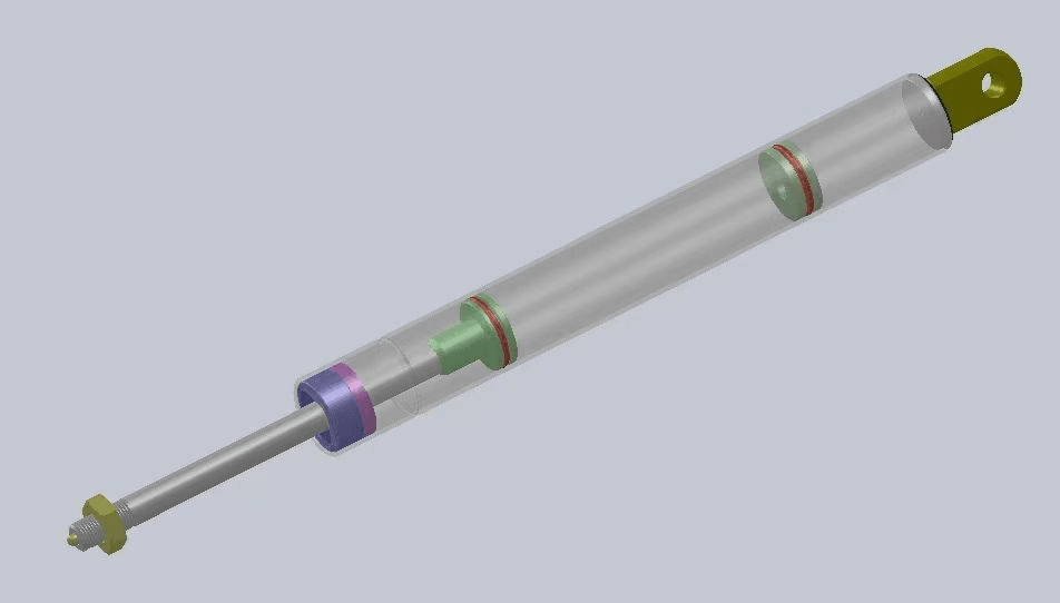
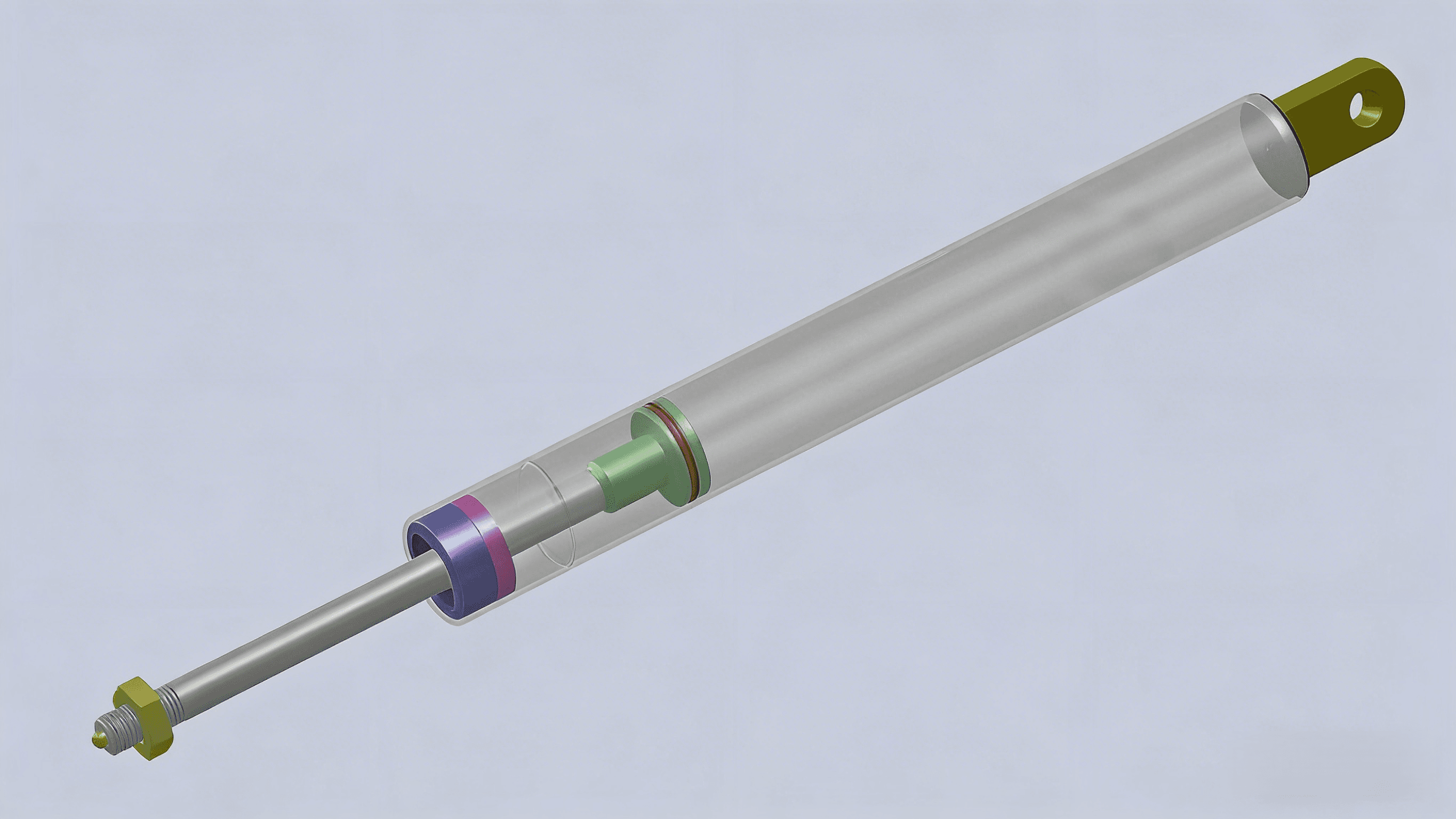
What is Adjustable Lockable Gas Spring?
DKG has a line of adjustable locking gas springs which look like traditional gas springs but can be locked in any position along the stroke. There's an internal locking mechanism that's actuated by a release pin located at the end of the rod. To fit your product requirements, we offer three types of adjustable locking gas springs:
Rigid in compression:
No movement when the rod is pushed, but some movement when the rod is pulled.

Rigid in extension:
No movement when the rod is pulled, but some movement when the rod is pushed.

High Load Capacity
Withstand lateral forces ≥ 2,000 N with reliable locking force plateau performance.

Rigid vs. Elastic: The Core Difference
Rigid Locking
The floating piston separates oil and gas into two chambers. The piston locks in the oil chamber, featuring strong locking force and zero displacement after locking. The nitrogen chamber is small with a high compression ratio.
- Zero Displacement – Completely rigid support
- Dual Chamber – Oil-gas separation with floating piston
- High Locking Force – ≥ 2,000 N lateral capacity
- Best For – Operating tables, tooling fixtures, aircraft bins
Elastic Locking
There is no floating piston, and only a single chamber exists. The chamber is filled with nitrogen and a small amount of hydraulic oil (for lubrication). It has slightly weaker locking force, minor displacement after locking, and a low compression ratio.
- Soft Rebound – Allows ≤ 5 mm elastic displacement
- Single Chamber – N₂ + lubricating oil mixture
- Cushioning Effect – Gentle positioning with damping
- Best For – Wheelchairs, hospital beds, office furniture
Detailed Selection Guide
Rigid Locking Characteristics
- • Minimal displacement under pull force in locked state (typically ≤ 2mm)
- • Ideal for precise positioning and absolute support
- • Applications: Medical beds, auxiliary instruments, precision equipment
- • Stroke Factor: 2.4 (relatively lower stroke utilization)
Rigid Locking Formulas
Given Stroke S, find minimum Extended Length:
Given Extended Length L, find maximum Stroke:
Elastic Locking Formulas
Given Stroke S, find minimum Extended Length:
Given Extended Length L, find maximum Stroke:
Dimension Rules:The ratio of cylinder diameter (D) to piston rod diameter (d) should not be less than 1.1. Standard series: KQ10/22, KQ10/28. Contact us for custom needs.
- Weight in Newtons: mass (kg) × 9.81
- One-spring force: F = 1.2 × (W × L) ÷ (B × 0.65)
- L = hinge-to-CG distance
- B = hinge-to-spring distance
- Use n springs? Divide F by n.
- For lockable springs, you also need to consider the locking force and friction, which might require specialized configurators.
- Complexity: Real-world applications involve changing geometry and dynamic forces;
Nominal Force (Fₙ)
The initial force during extension or compression. For Fₙ > 100N, use increments of 50N.
Support Force (Fₛ)
Ensure support force < 1.3 × Fₙ (max air pressure) for smooth lifting.
Locking Force (Fₗ)
Compression locking force for rigid gas springs should exceed:
Opening Force (Fₒ)
The force required to release the lock, typically determined by user needs.
Extension Speed
Standard requirement: 40mm/s ~ 200mm/s
Cycle Life
DKG gas springs reach 50,000 cycles with < 12% force decay.
Sealing Performance
No stroke change after 24 hours under rated force at any angle.
Environmental Adaptability
Must meet temp requirements (-30℃ to +60℃) and corrosion resistance.
Example: KQ 10/27 60 260 F350 indicates 10mm rod, 27mm cylinder, 60mm stroke, 260mm extended length, and 350N force.
Real-World Applications
Medical

- •Wheelchair backrests
- •Hospital bed height adjustment
- •Operating table positioning
Furniture & Office

- •Seat height adjustment
- •Keyboard tray positioning
- •Lifting display stands
Industrial

- •Tooling fixtures
- •Equipment positioning
- •Workstation adjustment
Aviation

- •Aircraft overhead bins
- •Cargo door control
- •Cabin equipment support
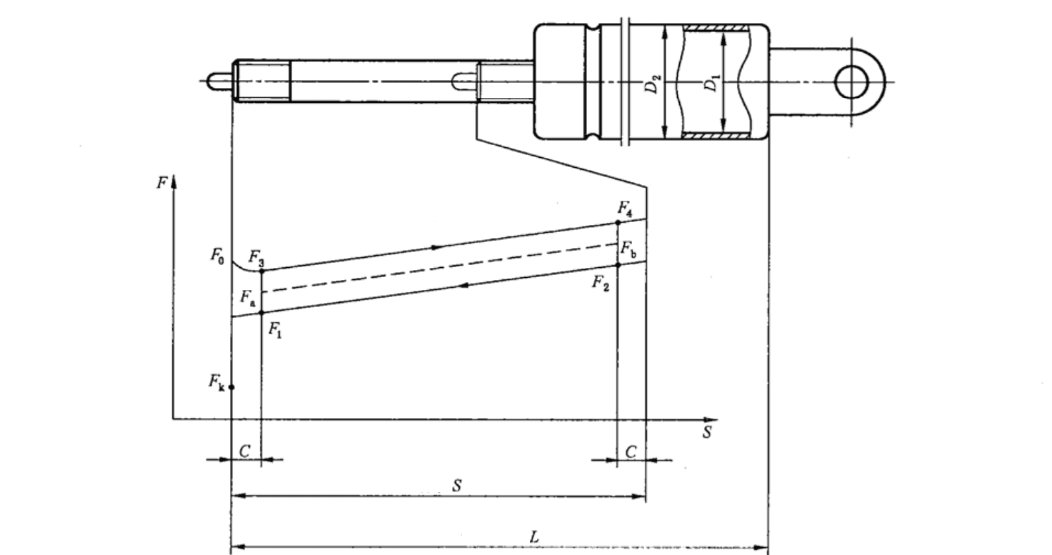
Locking Force Performance
The locking force curve shows the stability plateau—the higher and flatter the plateau, the more reliable the locking performance.
Default Configuration (Standard 165mm stroke)
Locking Force Curve for Standard 165mm Stroke
Rigid Locking
- • Long, stable plateau region
- • Theoretical spring ratio: 1.28–1.44
- • Superior load retention
- • Ideal for high-rigidity applications
Elastic Locking
- • Gradual force curve with cushioning
- • Softer load response
- • Better for comfort-focused applications
- • Gentle positioning with damping
Safety Selection Principle
Always ensure: Plateau Force ≥ Customer's Maximum Lateral Load × 1.5 Safety Factor
Precision Manufacturing Process
Every lockable gas spring undergoes rigorous quality control with specialized precision assembly steps.

Key Difference
Compared to standard gas springs, lockable versions include a critical precision assembly step for the floating piston, needle valve, and steel ball locking mechanism.
Quality Assurance
Force characteristic testing, pressure retention verification, and 10,000-cycle leakage testing ensure long-term reliability and performance.
We Solve Your Challenges
Long Lead Times
We reduce delivery from 8–12 weeks to 2–4 weeks as a direct replacement for Stabilus, Suspa, and Hahn products.
Micro-Movement After Locking
Switch to our Rigid Series (KQ10-28 Rigid) for zero-displacement performance.
Release Mechanism Mismatch
We offer full customization for ≤ Ø8 mm side pins or top buttons to fit your existing structure.
Missing Technical Drawings
We provide sample measurement + CAD + 3D PDF within 48 hours.
Incomplete Certifications
We deliver TS16949, ISO9001, RoHS, 96-hour salt spray, and SGS reports—all in one package.