

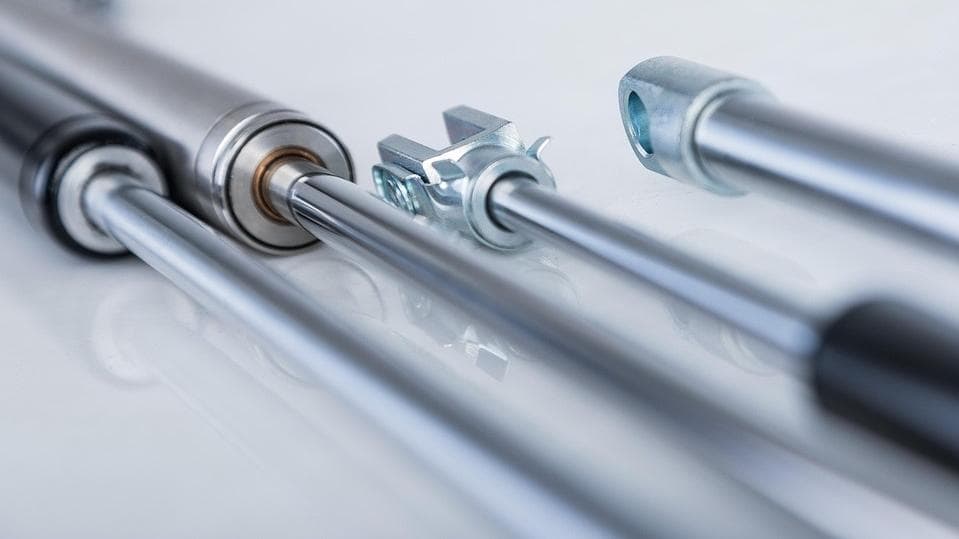
Industrial Gas Springs & Struts — Complete Product Range
Engineered for precision. Priced for scale. Explore our complete gas spring catalog featuring custom OEM/ODM solutions at highly competitive factory-direct prices.
Why Choose Direct Manufacturing? (Cost & Customization)
No middlemen, no premium markups — just factory-direct pricing that scales with your order volume.
No Middlemen
As a factory-direct custom gas springs manufacturer, we cut out distributors and pass the savings straight to you.
Tiered Wholesale Pricing
As your wholesale industrial gas struts supplier, our volume pricing scales with your order — the more you buy, the better the rate.
Competitive on Heavy Duty
Competitive-price heavy duty gas springs with custom force, stroke and end fittings — without the premium markup.
Bulk Order Discounts
Tiered pricing based on order volume. Share your target quantity and our engineers will return a factory-direct quotation.
| Volume Band | Unit Price | Sample Lead Time |
|---|---|---|
| 100–499 pcs | Request Quote | 12–15 days |
| 500–999 pcs | Request Quote | 10–12 days |
| 1000+ pcs | Request Quote | 7–10 days |
What is a gas spring?
Gas springs are hydro-pneumatic energy storage components. They consist of a precision piston rod moving within a sealed cylinder filled with pressurized nitrogen and oil.
No matter the position of the gas spring, the pressure around the piston is consistently uniform, due to the rod's small cross-sectional area. This is why gas springs provide more consistent and steady force than conventional coil springs.
The spring force (F) is calculated as the pressure differential (ΔP) between the internal and external environments acting on the piston rod cross-sectional area (A): F = ΔP × A.
Specifications can be tailored by adjusting nitrogen injected, oil quantity, and piston rod area to meet specific application requirements.
In high-pressure environments, the pressure difference ΔP must be carefully managed.
The following sections introduce different types of gas springs.
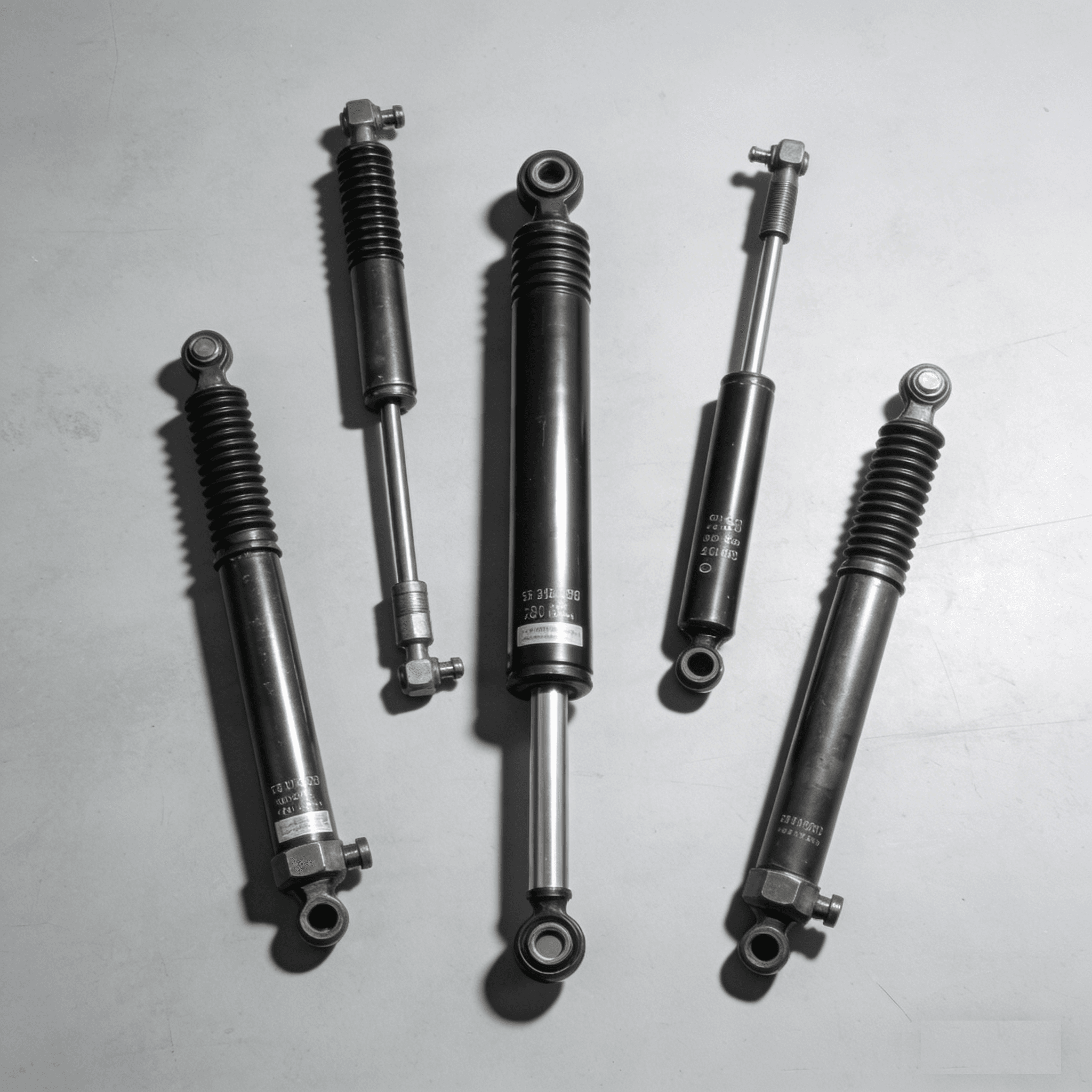
Product Series
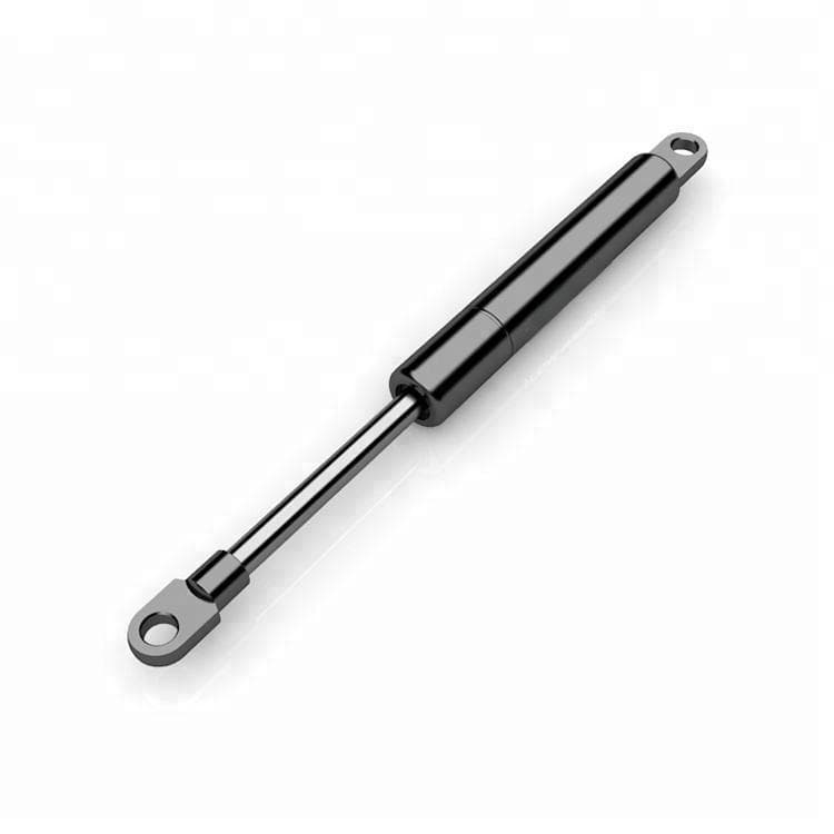
What is Compression Gas Spring?
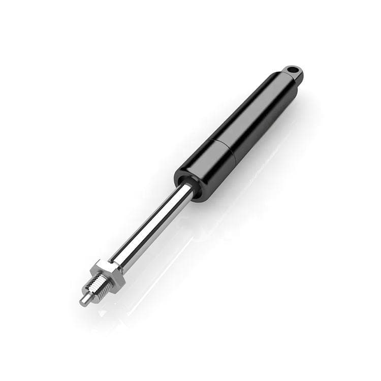
What is Lockable Gas Spring?
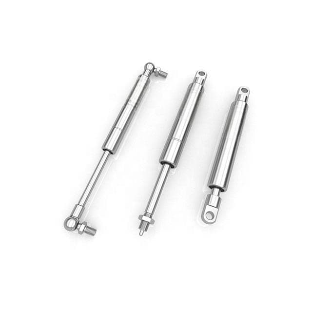
What is Stainless Gas Spring?
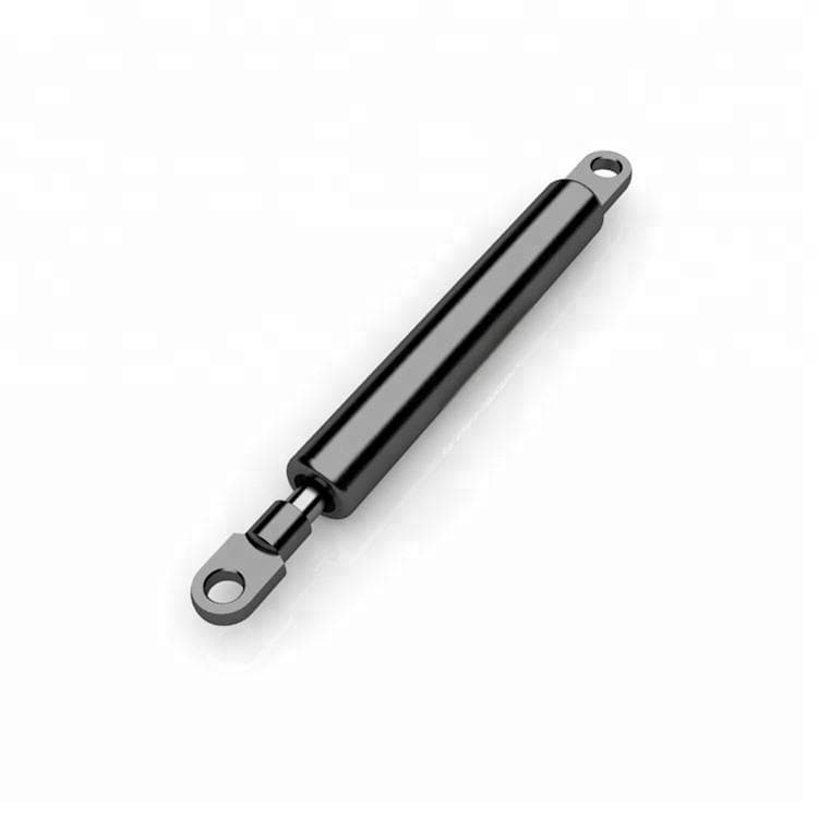
What is Tension Gas Spring?
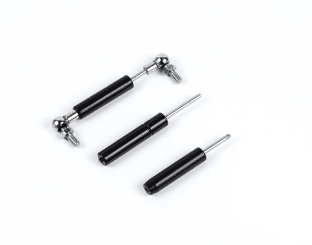
What is Micro Gas Spring?
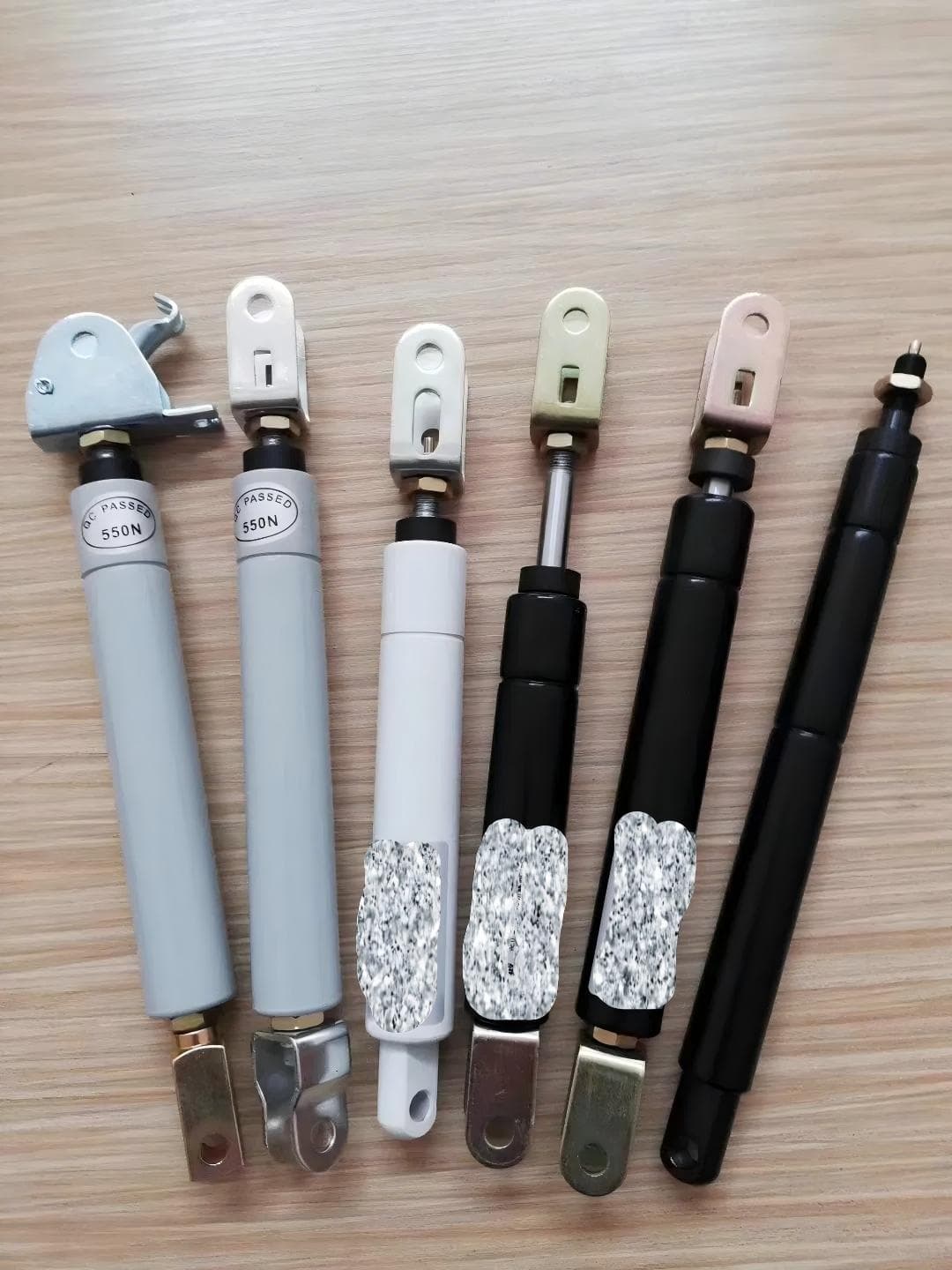
What is Push-to-unlock Gas Spring?
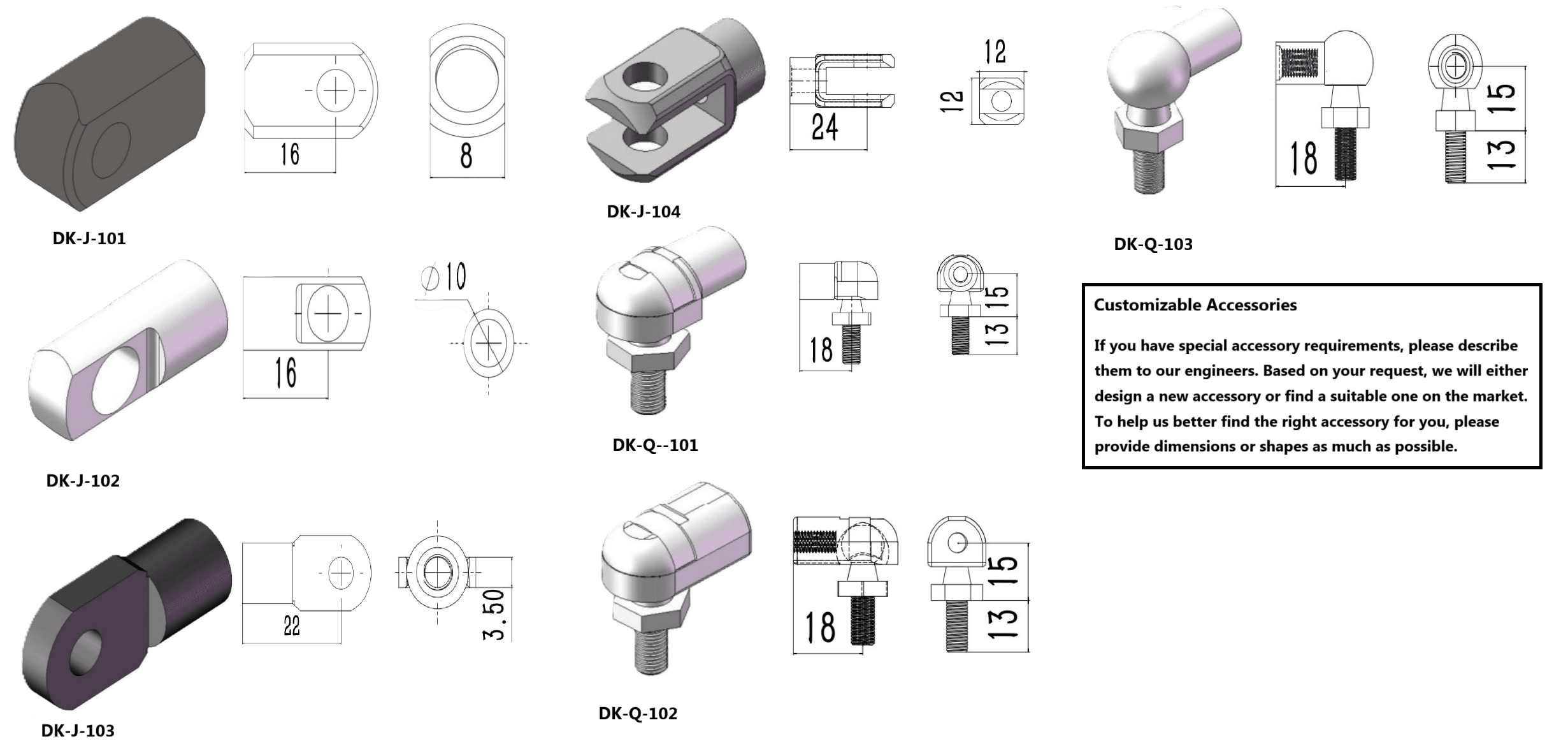
Accessories Series
How Gas Springs Work?
Gas springs—also known as gas struts or gas dampers—work by using compressed nitrogen gas as an elastic energy storage material within a sealed metal cylinder. The cylinder also contains a small amount of hydraulic oil (such as lubricating or damping oil). These oils serve three main functions:
- Support the gas sealed within the cylinder.
- Lubricate moving parts to reduce wear.
- Provide damping.
When you push the piston rod into the cylinder (this is the compression process), the space available for the nitrogen gas gets smaller. Just like squeezing a balloon makes the pressure inside go up, this smaller volume causes the gas pressure inside the cylinder to rise—this follows Boyle’s Law.
The force the gas spring puts out gets stronger as you push the rod in, and it is strongest when the rod is fully pressed into the cylinder. This more steady, reliable force than a coil spring is why gas springs are used in everyday things like car tailgates (to hold them open gently), industrial machines (to control movement), and ergonomic furniture (like adjustable office chairs).
Gas Spring Force Curve
If you look at the diagram above, you’ll see how the gas spring acts as the piston moves.
With gas springs, force increases progressively with a near-linear progression rate as they are compressed, requiring less initial force to compress them. As the gas spring nears the end of its stroke, the compression force needed rises.
Piston Extended State
When the piston is fully extended, the cylinder has the most space for gas.
Piston Compressed State
As the piston moves to fully compressed, the gas space shrinks—so the pressure goes up (you can see this on the solid line in the diagram). The dashed line shows how the cylinder volume decreases at the same time.
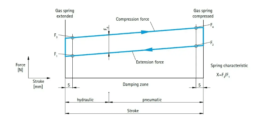
Force Characteristic
- F1 = extension force with extended piston rod.
- F2 = extension force with compressed piston rod.
- F3 = pull-in force with extended piston rod.
- F4 = pull-in force with compressed piston rod.
- FR = friction force.
The extension force is calculated by multiplying the filling pressure by the piston rod’s cross-sectional area. Size as well as force can be made according to your requirements.
DK standard gas springs offer extension forces from 10 N to 5000N, with tolerance is ± 5-7%.
The specified force (F₁) is always measured at 20°C ± 2°C, with the piston rod facing downward.
Physically, the actual force of a gas spring depends on the temperature. For each 10°C, the force changes by approx 3,3%.
A Critical Performance Measure: The K-Factor
To define how well a gas spring works, engineers use something called the K-factor (or gas spring progression rate). Put simply, this is the percentage change in force between two states:
Unloaded: When the piston is at P1 (fully extended, the spring’s starting position).
Fully loaded: When the piston is at P2 (fully compressed).
Good quality gas springs have a very low K-factor—usually between 1.05 and 1.8. For comparison, mechanical compression springs (like the coil ones we mentioned earlier) have much higher K-factors. A low K-factor means the spring’s force stays steady as it compresses—this is important for applications where you need consistent lifting or damping (like holding a heavy car tailgate at any angle).
One quick note for calculations: Gas springs are pre-charged to a specific force at P1 (we call this force F1)—so you should always use F1 as your starting point when figuring out the right gas spring for a job.
How to Choose a Gas Spring: Replacement by Code and Size?
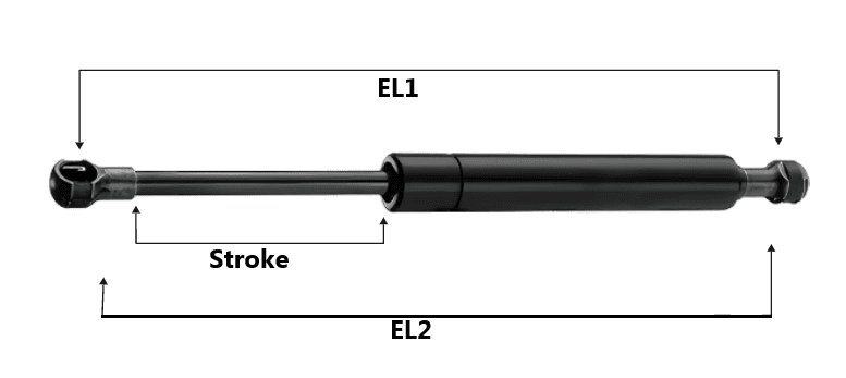
Replacement, according to code and size(key: EL2 / stroke / pressure)
- Stroke of a Gas Spring: This indicates the maximum range of motion of the rod, ranging from its fully retracted point to its fully extended point.
- EL1: Extended or Expanded Length: This term denotes the total length of the gas spring, measured from the midpoint of one end fitting to the midpoint of the opposite end fitting.
- EL2: If no end fittings are specified, it pertains to the length from the rod end to the tube end.
Select Product Type
Enter Specifications
How to Choose a Gas Spring: A Simple Guide for Engineers
You, as an engineer, have a certain problem which has to do with controlled movement and needs to be solved without extra engergy? Follow questions to get your selection done.We can assist you in selecting the proper gas spring for your application—and also can help with the design!
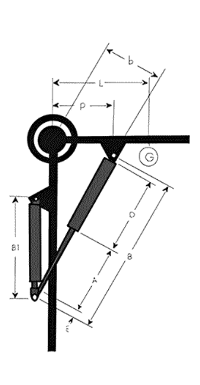
Parameters Definition
Determination of minimum extension force F1
In the F1=KGL / bn formula:
F1=Minimum extension force(Unit:N)
G=Door Weight(Unit:kg)
L=Distance between the center of gravity to the Center of gyration(Unit:mm)
b=Effective force arm when the gas spring extends(Unit:mm)
n=Number of gas spring
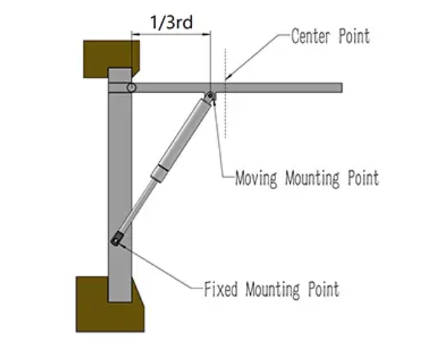
P=Mounting position on the gas spring door, namely about 1/3L away from the center of gyration.
K=Safety factor(11 generally)
G=30kg, L=400 mm, n=2, b=200mm and F1=30x400x11/(200x2)=330N
S=Stkore
EL1=Extended or Expanded Length
Calculation Formula & Parameters
Here’s how it works:
1. Simple Sketch – Provide a basic drawing (like the example on the top) showing:
2. We Handle the Rest! – Send us your sketch, and we’ll recommend the best gas spring for your needs.
It’s that easy! Just share your requirements, and we’ll take care of the rest.
Extension Force Calculation
Force Calculation
These values can be influenced, e.g.by the gas volume or the oil quantity. A special characteristic of DK gas springs is the low friction figure.Through the combinations of different nozzle orifices and oil quantity, its possible to control the push-out and pushin speed as required.
F = p × ABasic Principle
Gas spring : Selection of Installation Location
Third-Party Test Reports by Series
Independent laboratory evidence instead of marketing claims. Each gas spring series is validated for corrosion, substance compliance and fatigue life — view the full original reports.
Salt Spray Test (ISO 9227 NSS)
96–244 hours of continuous exposure without red rust on SS316 cylinders.
RoHS Substance Compliance
All six controlled substances measured below limit values — full PASSED results.
50,000-Cycle Lifecycle Test
Force decay remains within tolerance after 50,000 compression cycles.

Ryan Chen
Senior Project Manager & Industrial Hardware Specialist
“Dedicated to helping global distributors eliminate after-sales risks through precision-calibrated hardware solutions.”