

Lockable Gas Spring Manufacturer | Elastic & Rigid Locking Gas Struts
DK Lockable Gas Springs (locking gas struts) deliver smooth motion control and multi-position locking for medical beds, office furniture, passenger seats, and industrial equipment. Tailored for global OEMs and distributors, our locking gas springs offer configurable strokes, force ratings, release mechanisms, and locking types (rigid or elastic). We provide custom engineering, rapid sampling, and OEM-grade replacements to fit your exact application specs.
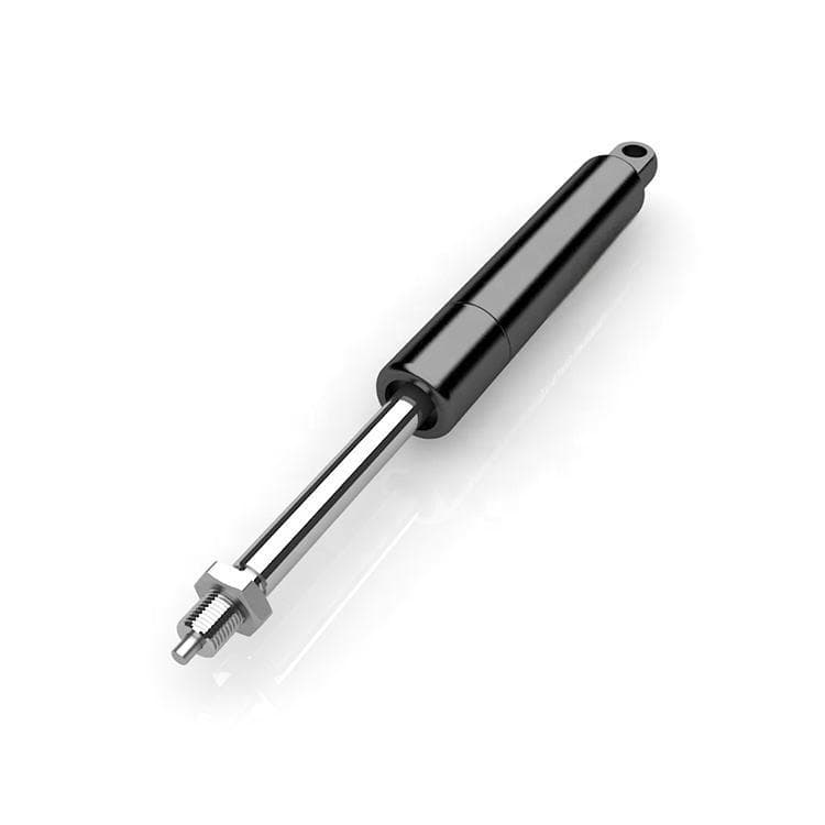
What is Adjustable Lockable Gas Spring?
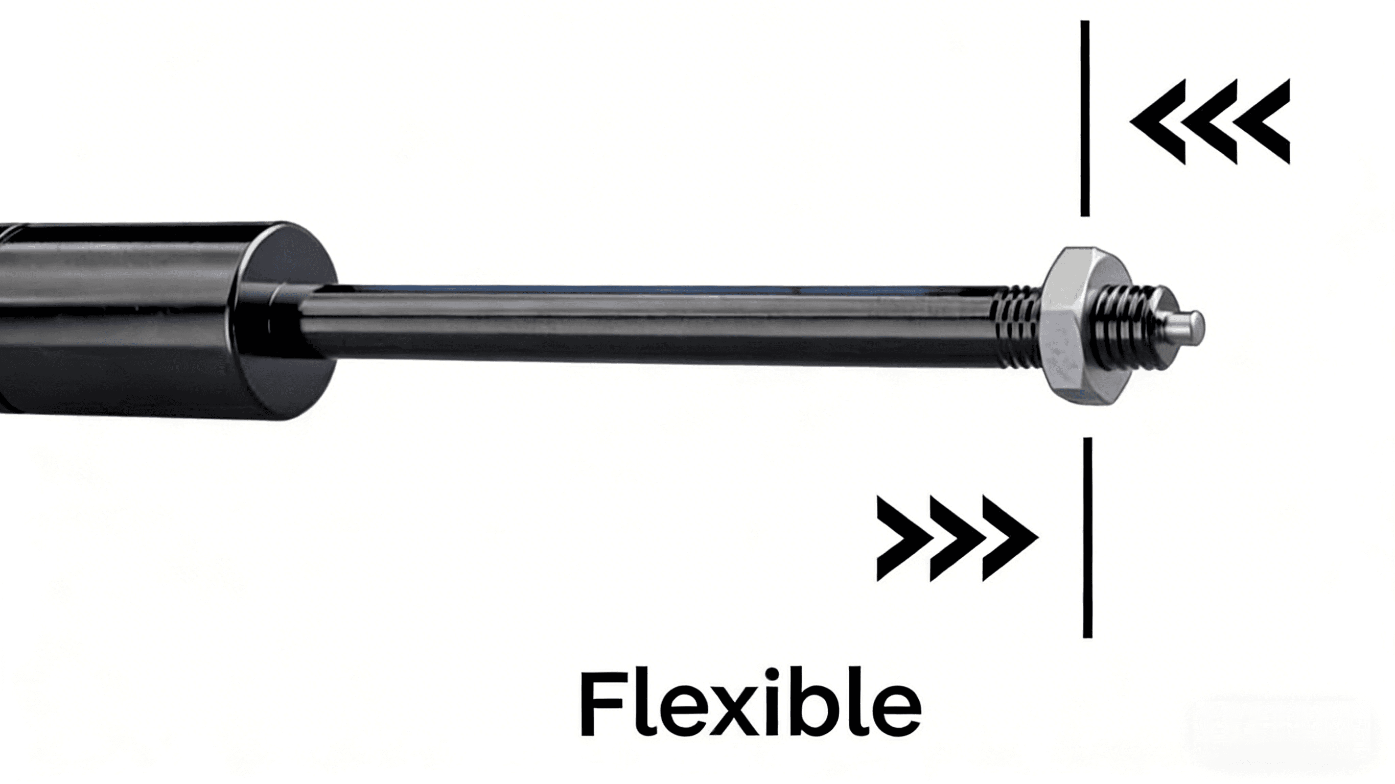
DKG has a line of adjustable locking gas springs which look like traditional gas springs but can be locked in any position along the stroke. There's an internal locking mechanism that's actuated by a release pin located at the end of the rod. To fit your product requirements, we offer three types of adjustable locking gas springs:
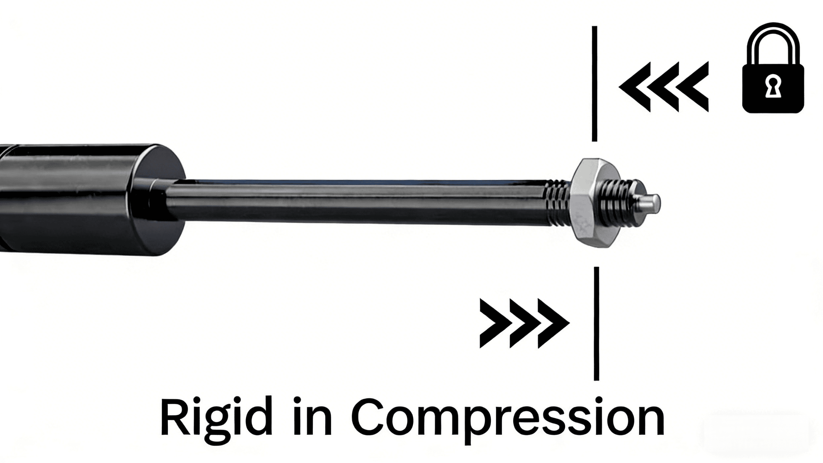
Rigid in compression:
No movement when the rod is pushed, but some movement when the rod is pulled.
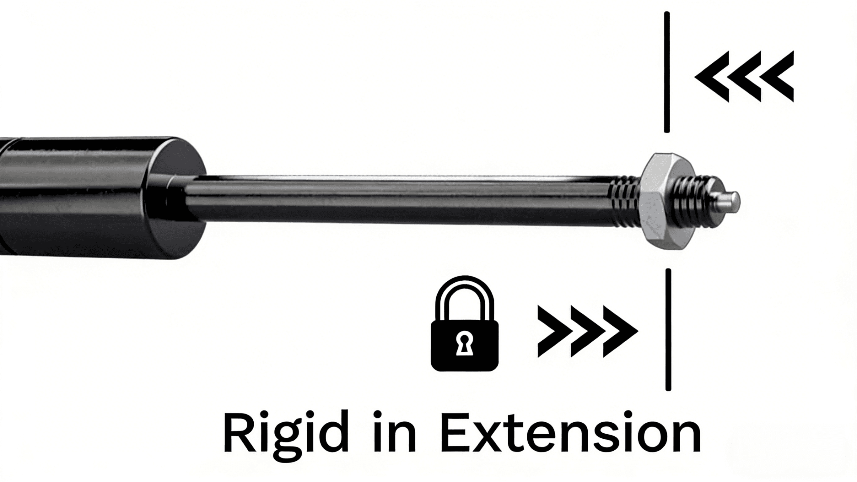
Rigid in extension:
No movement when the rod is pulled, but some movement when the rod is pushed.
High Load Capacity
Withstand lateral forces ≥ 2,000 N with reliable locking force plateau performance.
Rigid vs. Elastic: The Core Difference
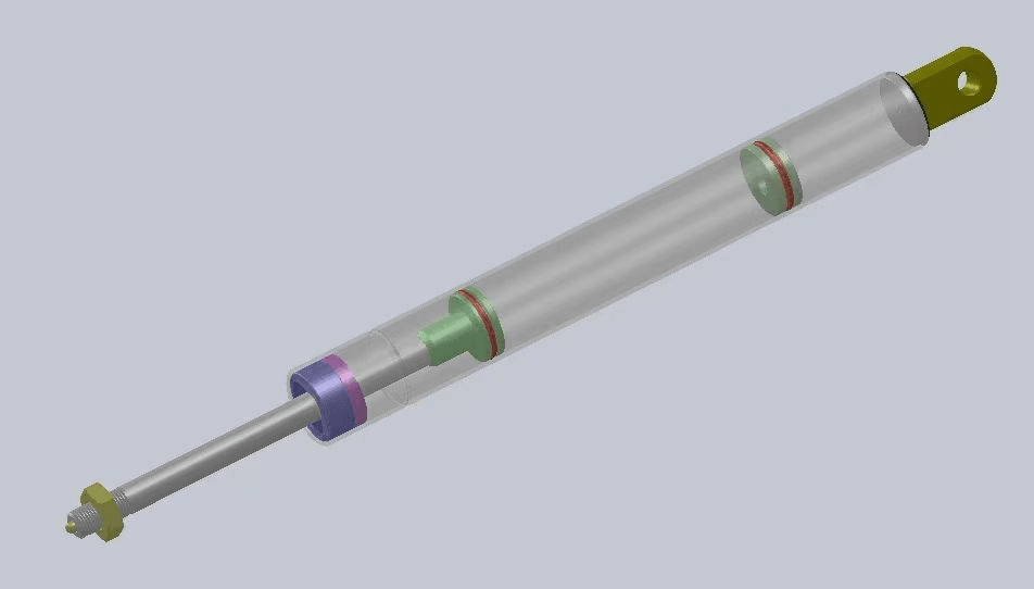
Rigid Locking
The floating piston separates oil and gas into two chambers. The piston locks in the oil chamber, featuring strong locking force and zero displacement after locking. The nitrogen chamber is small with a high compression ratio.
- Zero Displacement – Completely rigid support
- Dual Chamber – Oil-gas separation with floating piston
- High Locking Force – ≥ 2,000 N lateral capacity
- Best For – Operating tables, tooling fixtures, premium overhead bins
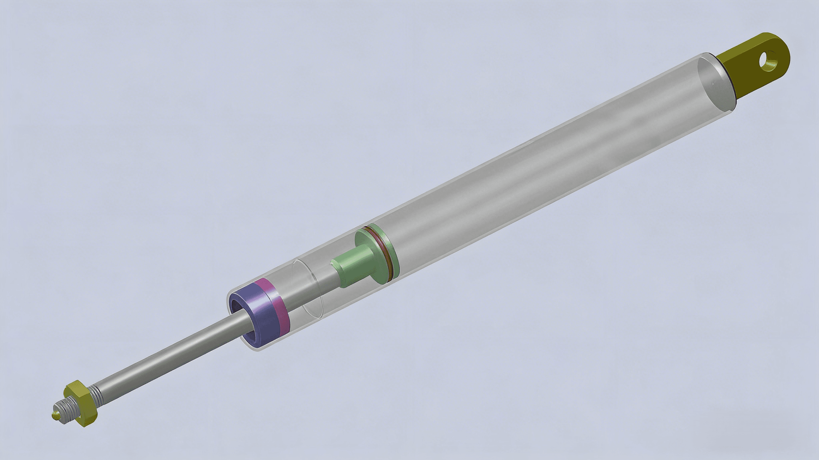
Elastic Locking
There is no floating piston, and only a single chamber exists. The chamber is filled with nitrogen and a small amount of hydraulic oil that delivers hydraulic damping for gentle positioning. It has slightly weaker locking force, minor displacement after locking, and a low compression ratio. As a specialist in hydraulic-damped gas springs, DK calibrates oil volume and orifice size for smooth, controlled motion.
- Soft Rebound – Allows ≤ 5 mm elastic displacement
- Single Chamber – N₂ + lubricating oil mixture
- Cushioning Effect – Gentle positioning with damping
- Best For – Wheelchairs, hospital beds, office furniture
Release Mechanisms
Select the release method that fits your mechanical linkage and operator workflow.
Detailed Selection Guide
Rigid Locking Characteristics
- • Minimal displacement under pull force in locked state (typically ≤ 2mm)
- • Ideal for precise positioning and absolute support
- • Applications: Medical beds, auxiliary instruments, precision equipment
- • Stroke Factor: 2.4 (relatively lower stroke utilization)
Rigid Locking Formulas
Given Stroke S, find minimum Extended Length:
Given Extended Length L, find maximum Stroke:
Elastic Locking Formulas
Given Stroke S, find minimum Extended Length:
Given Extended Length L, find maximum Stroke:
Dimension Rules:The ratio of cylinder diameter (D) to piston rod diameter (d) should not be less than 1.1. Standard series: KQ10/22, KQ10/28. Contact us for custom needs.
- Weight in Newtons: mass (kg) × 9.81
- One-spring force: F = 1.2 × (W × L) ÷ (B × 0.65)
- L = hinge-to-CG distance
- B = hinge-to-spring distance
- Use n springs? Divide F by n.
- For lockable springs, you also need to consider the locking force and friction, which might require specialized configurators.
- Complexity: Real-world applications involve changing geometry and dynamic forces;
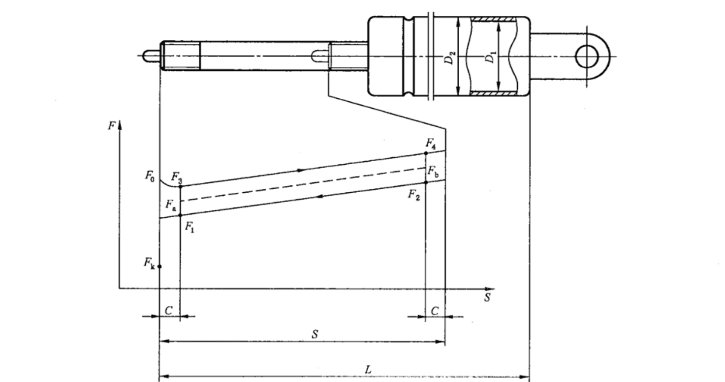
Nominal Force (Fₙ)
The initial force during extension or compression. For Fₙ > 100N, use increments of 50N.
Support Force (Fₛ)
Ensure support force < 1.3 × Fₙ (max air pressure) for smooth lifting.
Locking Force (Fₗ)
Compression locking force for rigid gas springs should exceed:
Opening Force (Fₒ)
The force required to release the lock, typically determined by user needs.
Extension Speed
Standard requirement: 40mm/s ~ 200mm/s
Cycle Life
DK gas springs reach 50,000 cycles with < 12% force decay.
Sealing Performance
No stroke change after 24 hours under rated force at any angle.
Environmental Adaptability
Must meet temp requirements (-30℃ to +60℃) and corrosion resistance.
Example: KQ 10/27 60 260 F350 indicates 10mm rod, 27mm cylinder, 60mm stroke, 260mm extended length, and 350N force.
| Industry Series | Rod (mm) | Tube (mm) | Recommended Stroke (mm) | Force Range (N) | Industry Cross-Reference | Mainstream Industrial Uses |
|---|---|---|---|---|---|---|
| 08/22 | 8 | 22 | 20 - 300 | 50 - 400 | Office chair backrests; simple height-adjustable tables and chairs | |
| 10/22 | 10 | 22 | 20 - 400 | 100 - 800 | Bansbach K01/Stabilus Standard | Lightweight medical examination chairs; physiotherapy equipment |
| 10/28 | 10 | 28 | 20 - 500 | 100 - 1000 | Special configuration combining low insertion force with high gas volume | Compact high-resilience locking applications |
| 12/28 | 12 | 28 | 30 - 600 | 200 - 1500 | Stabilus BLOC-O-LIFT Heavy-Duty/SUSPA K1 | Hospital bed backrests; protective covers for heavy equipment |
| 12/30 | 12 | 30 | 30 - 700 | 300 - 2000 | Bansbach K03/Heavy-Duty Industrial | Railway seating; marine and special-purpose hatches |
Benchmark references indicate comparable industry series for a first-pass review only. Equivalence with any brand or model requires dimensional and force verification against your sample or drawing before ordering.
Real-World Applications
Medical
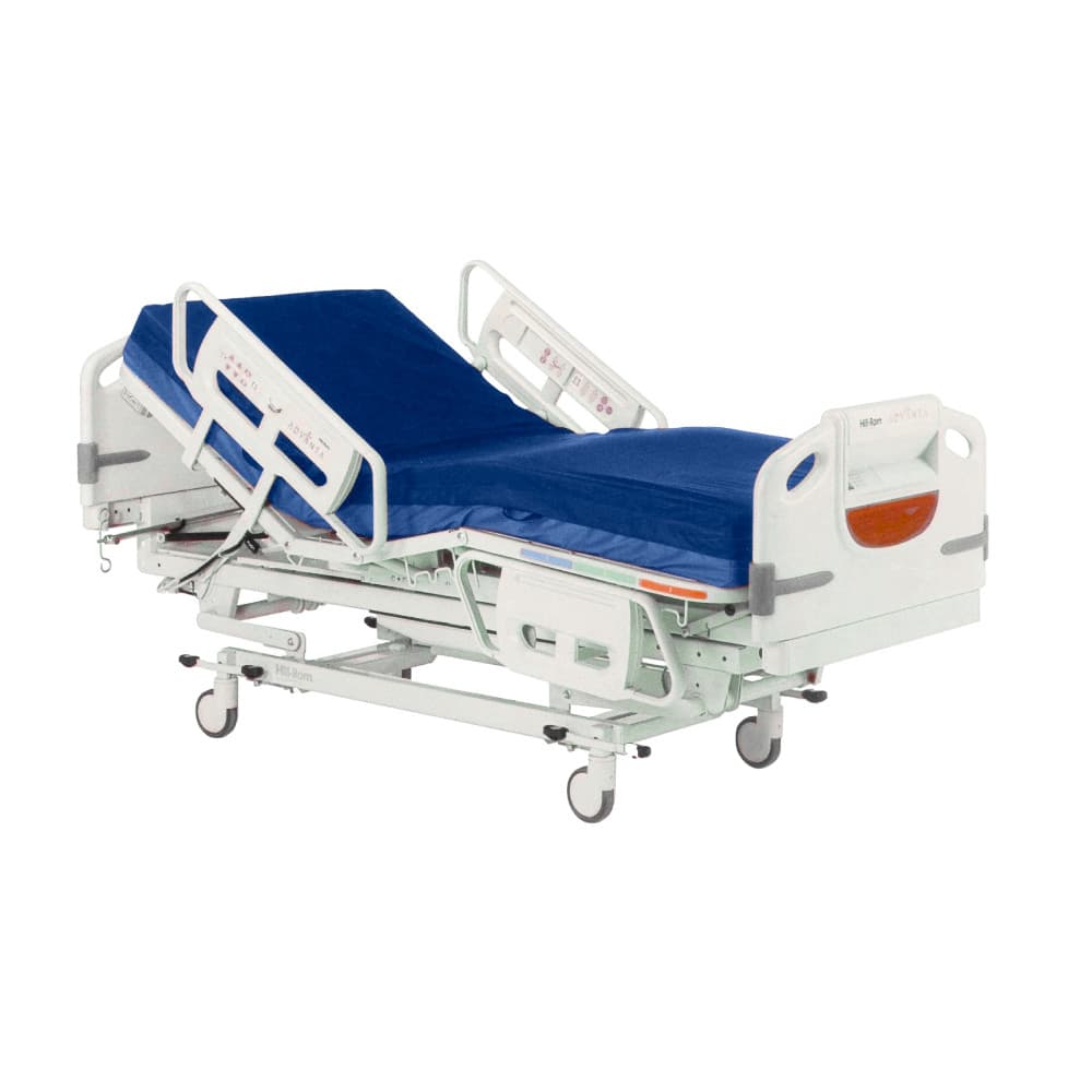
- •Wheelchair backrests
- •Hospital bed height adjustment
- •Operating table positioning
Furniture & Office
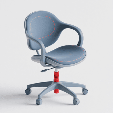
- •Seat height adjustment
- •Keyboard tray positioning
- •Lifting display stands
Industrial
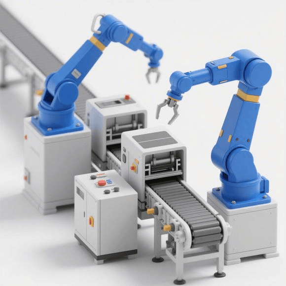
- •Tooling fixtures
- •Equipment positioning
- •Workstation adjustment
Cabin & Cargo

- •Premium overhead bins
- •Cargo door control
- •Cabin equipment support
Locking Force Performance
The locking force curve shows the stability plateau—the higher and flatter the plateau, the more reliable the locking performance.
Default Configuration (Standard 165mm stroke)
Locking Force Curve for Standard 165mm Stroke
Rigid Locking
- • Long, stable plateau region
- • Theoretical spring ratio: 1.28–1.44
- • Superior load retention
- • Ideal for high-rigidity applications
Elastic Locking
- • Gradual force curve with cushioning
- • Softer load response
- • Better for comfort-focused applications
- • Gentle positioning with damping
Safety Selection Principle
Always ensure: Plateau Force ≥ Customer's Maximum Lateral Load × 1.5 Safety Factor
Precision Manufacturing Process
Every lockable gas spring undergoes rigorous quality control with specialized precision assembly steps.
Key Difference
Compared to standard gas springs, lockable versions include a critical precision assembly step for the floating piston, needle valve, and steel ball locking mechanism.
Quality Assurance
Force characteristic testing, pressure retention verification, and 10,000-cycle leakage testing ensure long-term reliability and performance.
We Solve Your Challenges
Long Lead Times
We reduce delivery from 8–12 weeks to 2–4 weeks as a direct replacement for Stabilus, Suspa, and Hahn products.
Micro-Movement After Locking
Switch to our Rigid Series (KQ10-28 Rigid) for zero-displacement performance.
Release Mechanism Mismatch
We offer full customization for ≤ Ø8 mm side pins or top buttons to fit your existing structure.
Missing Technical Drawings
We provide sample measurement + CAD + 3D PDF after the drawing scope is confirmed.
Incomplete Certifications
Quality and test documents are available per configuration on request.
Frequently Asked Questions
Procurement & Logistics Guide
MOQ & Samples
Low MOQ supported, with rapid sample customization and testing available for your application.
Lead Time
Delivery schedule is based on engineering review and sample confirmation, finalized at RFQ confirmation.
RFQ Checklist
Provide the following for a fast and accurate quotation:
- 1.Locking type (rigid or elastic) and mounting orientation
- 2.Stroke (S) and extended length (L)
- 3.Nominal force (F₁) and locking force requirements
- 4.End fittings and release pin specifications
- 5.Application scenario and drawings (if available)
Related Resources
Explore related product categories and selection guides:
Rigorous Mechanical Fatigue & Lifecycle Testing
The core pain point for B2B buyers is batch failure caused by mechanical fatigue and the resulting high after-sales repair costs. Our product has passed the official SGS full-stroke reciprocating cycle test.
Methodology
An appropriate force is applied to the piston rod to move it from the fully extended position to the fully compressed position. The force is then removed, allowing the rod to return to the fully extended position. This cycle is repeated 50,000 times.
Requirement
After the test, the sample shall not exhibit any damage, jamming, or functional loss.
Final Status
PASSED — No damage, no functional loss
SGS Tested Sample Record (Sample ID: SHA21-033925.001)
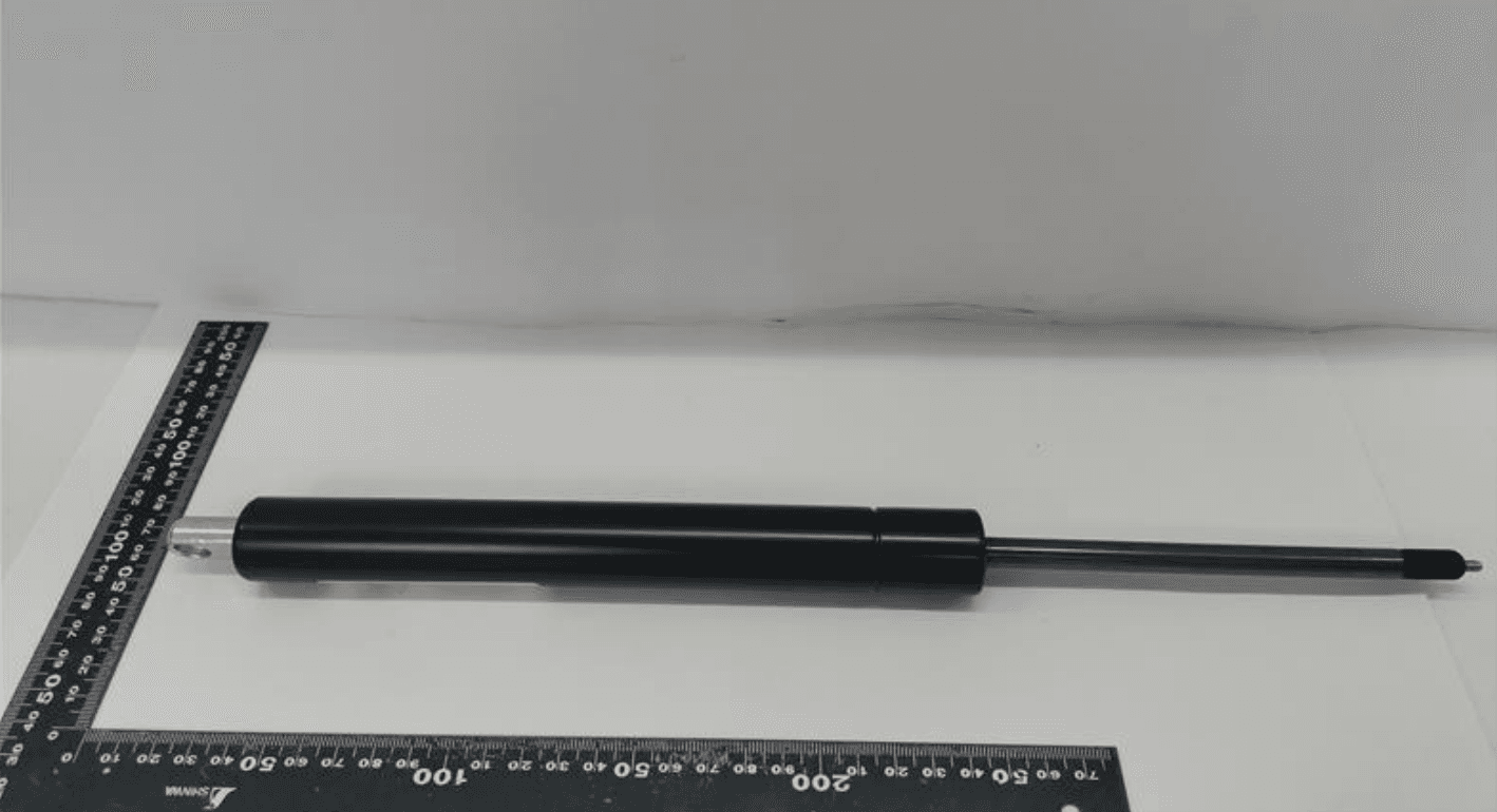
Gas spring fatigue test live video
- 1. The statement of conformity is based on a decision rule of non-binary decision with a guard band (guard band length parameter is 0).
- 2. This report is the official original English report (SHHL2103007983FT) issued by SGS, possessing full international traceability and validity.

Ryan Chen
Senior Project Manager & Industrial Hardware Specialist
“Dedicated to helping global distributors eliminate after-sales risks through precision-calibrated hardware solutions.”