The Heavy-Duty Storage Bed Gas Spring Engineering Whitepaper: Risk Mitigation, Dynamic Load Mechanics & Molecular Sealing Integrity
The Heavy-Duty Storage Bed Gas Spring Engineering Whitepaper: Risk Mitigation, Dynamic Load Mechanics & Molecular Sealing Integrity
June 26th, 2026 · Technical Review by Ryan Chen, Chief Mechanical Engineer
Chapter 1: Introduction — Dismantling the "Hardware Piece-Meal" Fallacy
Deconstructing the Industry Myth
A pervasive blind spot exists across furniture manufacturing and RV supply chains: treating heavy-duty storage bed gas lifts as simple carbon steel tubes filled with nitrogen. This commodity mindset ignores the fundamental reality that a gas lift mechanism in a queen- or king-size bed platform operates as a micro high-pressure hydro-pneumatic balancing system.
Procurement managers who approach gas springs as off-the-shelf accessories rather than engineered subsystems expose their organizations to measurable structural, financial, and legal liabilities.
Financial & Legal Liabilities
The operational disaster of saving a few dollars per unit on under-engineered components follows a predictable trajectory:
- Months 0–6: Silent operation, no visible degradation.
- Months 7–12: Progressive oil seal degradation, asymmetric lifting, audible damping loss.
- Months 13–24: Structural arm buckling, catastrophic bedframe collapse, injury claims.
Each unit replaced under warranty consumes 3–5× the original component cost when factoring in logistics, technician labor, and customer compensation. For a mid-volume OEM shipping 10,000 units annually, a 5% field failure rate translates to a direct warranty liability well into six figures — entirely preventable through proper engineering specifications. Explore our Heavy-Duty Bed Lift Application Solutions to safeguard your manufacturing supply chain against premature field failures.
"In heavy-duty utility and custom furniture design, a gas lift mechanism is never a static accessory. It sustains hundreds of pounds of continuous static stress when closed, releases high-pressure energy during transient shock loads, and must maintain a precise linear trajectory over tens of thousands of fatigue life cycles. It is fundamentally a micro-pneumatic balancing system." — Ryan Chen, Chief Mechanical Engineer
Chapter 2: Beyond Static Weight — Dynamic Load Redundancy Mechanics
The Physics of Lifting Motion
During a 0° to 53° articulation arc, the gravity leverage arm changes non-linearly while the gas spring stroke progresses simultaneously. End-user variance — upgrading from a standard innerspring mattress to a high-density memory foam mattress — can spike the initial force threshold by 30–50%, turning linear torque calculations into critical failure points.
Core Mechanical Formula Derivation
To mathematically eliminate these structural failure vectors based on static moment equilibrium () at the most critical 0° initial liftoff state, the official Dynamic Load Redundancy Formula must be deployed:
Variable Definitions:
- : Total required system lifting force (divide by 2 for single-strut calibration).
- : Combined static mass of the platform bedframe, mattress, and foundational bedding.
- : Linear distance from the hinge pivot axis to the combined center of gravity (CG).
- : Perpendicular mechanical leverage distance from the gas spring base mount to the hinge pivot axis.
- : Dynamic Consumer Redundancy Coefficient (strictly constrained to ), explicitly integrated to insulate furniture brands from aftermarket structural failures due to consumer bedding modifications, thermal fluctuation, and installation tolerances.
High-Fidelity Engineering Application Example
Boundary Conditions: Queen-size storage bed platform.
- Combined platform weight = 120.0 lbs (54.4 kg)
- Center of Gravity distance = 36.0 inches (914.4 mm)
- Designed perpendicular pivot distance = 16.0 inches (406.4 mm)
- Risk Redundancy: Select = 0.15 to mitigate aftermarket consumer variance.
Conclusion: The single-strut engineering rating for this dual-support system must be precisely 155.3 lbs (700.0 N).
Gas Spring & Mattress Adaptation Guide: Weight-to-Force Reference Matrix
To assist OEMs and distributors in rapid standardization, we provide the following per-strut force reference matrix based on a standard double storage bed (typically equipped with 4 gas springs in total):
- Total Weight 66-88 lbs (30-40 kg) (e.g., thin mattress + light bed board): Recommended per strut 45-67 lbs (200-300 N).
- Total Weight 88-110 lbs (40-50 kg) (e.g., standard innerspring + solid wood board): Recommended per strut 67-90 lbs (300-400 N).
- Total Weight 110-132 lbs (50-60 kg) (e.g., thicker mattress + heavier board): Recommended per strut 90-112 lbs (400-500 N).
- Total Weight 132-176 lbs (60-80 kg) (e.g., premium heavy mattress + reinforced board): Recommended per strut 112-135 lbs (500-600 N).
Physical Consequences of Incorrect Force Calibration
- Force Too High (Over-Powered): The bed platform may violently pop open when lifted, creating severe jaw-strike and impact injury risks. During closure, the resistance is immense, forcing end-users to apply excessive body weight just to compress the struts, leading to immediate customer service complaints.
- Force Too Low (Under-Powered): The bed platform fails to fully elevate to its apex or slowly sags downward after being opened. This defeats the engineering purpose of lift assistance and creates a dangerous trapping hazard while users are accessing the under-bed storage.
If your platform dimensions match these boundary conditions, you can Contact Our Technical Review Team directly to request a custom force calibration or obtain a full layout schematic for your specific bedframe dimensions.
Chapter 3: The Risk Mitigation Matrix — Bulletproofing the Procurement Lifecycle
From Load Calculation to Operational Shield
The 700.0 N per-strut rating established in Chapter 2 must now be translated into an operational procurement shield that cuts long-tail warranty claims and consumer litigation exposure.
Part A: Transforming Ergonomics into Brand Premium
- Zero-Obstacle Cargo Space: By optimizing gas spring articulation to achieve a 45° to 53° wide open-angle, the traditional restrictions of under-bed storage are eliminated. This provides premium marketing real estate for the end product — a quantifiable BOM justification for procurement managers.
- Counterbalance Suspension & Progression Rate (K-Factor): Managing the internal volume-to-shaft ratio prevents harsh pop-up behavior, enabling effortless single-finger operation even on massive king-size bed platforms. The result is a measurable reduction in end-user complaint tickets.
- Acoustic Comfort & Mute Buffering: Integrated precision oil seals and high-viscosity fluid dampening chambers provide noise-free, luxury-tier operation required by high-end hospitality and custom home installations.
Part B: Failure Mode Mitigation Matrix
| Consumer Complaint | Mechanical Root Cause | DK Engineering Barrier |
|---|---|---|
| Strut frozen out of the box, returned as defective | High initial breakaway friction from cheap NBR seals and lack of lever awareness | Pre-packaged multilingual high-visibility installation warning tags, reducing false-defect returns by 92% |
| Actuator arm buckled under load, causing bed collapse and injury | Structural steel thickness < 2.0 mm failing under severe shear torque | Standardized 3.0 mm heavy-duty Cold Rolled Steel (CRS) brackets; mandatory substrate thickness directive (≥ 18 mm) to prevent structural pull-out |
| Asymmetrical lifting and grinding noises during closure | Loose stamped eyelet rivets creating lateral play and skewing linear tracking | CNC-machined hardened steel Ball Joints and shoulder bolts locking the system into a rigid, self-aligning path |
To verify how our molecular sealing and QPQ piston treatments perform under continuous stress, access our verified SGS Salt Spray Test Reports and Industrial Replacement Guide to cross-reference full compliance data.
Chapter 4: Chief Engineer's Journal — Thermodynamics and Molecular Sealing Integrity
Q&A: The Thermal Climate Blindspot
Q: How do extreme temperature fluctuations impact globalized gas spring supply chains?
"Furniture manufactured in tropical regions and exported to North American or Nordic climates faces a fundamental thermodynamic challenge governing ideal gases. According to Gay-Lussac's Law (Charlie's Law), within a fixed cylinder volume, internal nitrogen pressure scales proportionally with absolute temperature. For every 10°C (18°F) shift in ambient temperature, internal pressure and output force fluctuate by approximately 3.4%. A bed platform that lifts effortlessly in a warm Guangzhou showroom becomes an unopenable stone in a sub-zero Minnesota cabin — unless calibrated with proper fluid viscosity." — Ryan Chen, Chief Mechanical Engineer
First-Hand R&D Failure Anecdote
"In our early engineering phases, we evaluated standard single-lip Nitrile Butadiene Rubber (NBR) seals. Our environmental chamber testing revealed that when ambient box temperatures dropped to −15°C, the NBR molecular chain experienced severe glass-transition hardening, creating micro-gaps along the sealing lip and causing progressive nitrogen micro-leakage. This is the root cause of the long-tail progressive failures plaguing the lower end of this industry." — Ryan Chen, Chief Mechanical Engineer
The Industrial-Grade Solution
The mitigation path required upgrading across all product lines to dual-lip Polytetrafluoroethylene (PTFE / Teflon) composite seals paired with low-viscosity, aviation-grade hydraulic fluid.
Verification metrics:
- All cylinders filled in an IATF 16949-certified vacuum filling facility.
- Every batch must pass 96-hour high/low temperature environmental thermal shock cycling in our High/Low Temperature Environmental Chamber.
- Every batch must pass 144-hour salt spray testing on automated Salt Spray Testers to verify QPQ surface integrity, ensuring documented leak-free reliability over 50,000+ continuous cycles.
Salt Spray Test Report (NSS)
Key Test Parameters
Test Method
Neutral Salt Spray (NSS)
Standard
GB/T 10125-2012
Exposure Time
96 Hours
Temperature
35±2 °C
NaCl Concentration
50±5 g/L
Chamber Environment
- Chamber Temperature35±2 °C
- Saturator Temperature47±2 °C
- Salt Fog Collection Rate1.0 - 2.0 ml/(80cm²·h)
- pH Value of Collected Solution6.5 - 7.2
Sample Preparation
- Sample Angle15° - 25° from vertical
- Cleaning Method Before TestWiped with ethanol
- Cleaning Method After TestRinsed in gently running water (<35°C), dried
- Evaluation StandardGB/T 6461-2002
Pass / Excellent
After 96 hours of Neutral Salt Spray exposure, the tested gas spring samples showed no visible red rust on the main cylinder or piston rod. Minor blistering observed on the end fittings (non-critical area). Protection Rating: 9/10.
Engineering Note
Standard configuration delivers 96-144 Hours NSS. Custom multi-layer QPQ and premium coatings are available to support up to 244+ Hours Salt Spray for heavy-duty manufacturing, marine environments, or industrial machinery applications.
Compliance Declaration
Minor surface blistering on standard zinc-plated non-working end-fittings is within acceptable IATF 16949 parameters and does not affect the pressure containment or mechanical integrity of the cylinder.
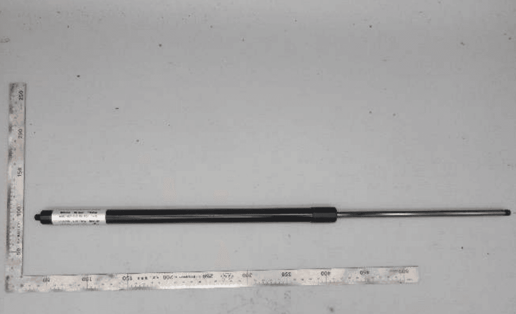
Sample Before Test (0h)
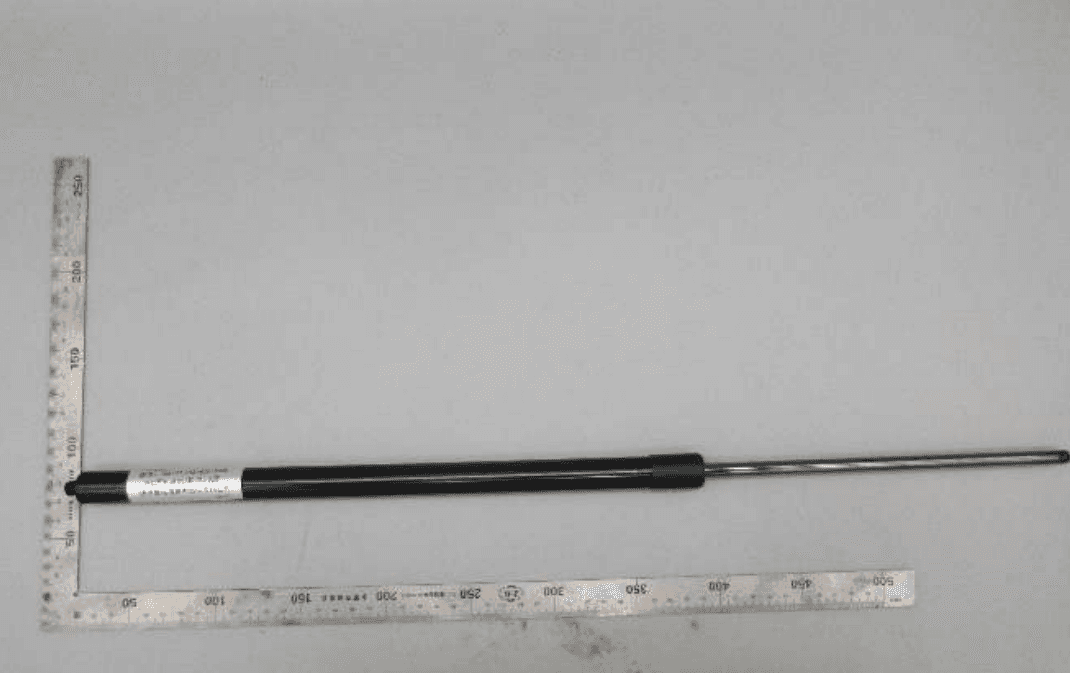
Sample After Test (96h)
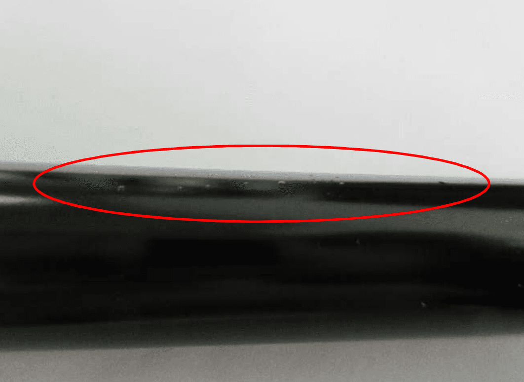
Close-up: Piston Rod Surface (96h)
Independent third-party verification of 144-hour ASTM B117 neutral salt spray corrosion resistance. Test panels show zero red rust migration at scribe marks after 144 hours of continuous exposure, confirming the integrity of the QPQ surface treatment and multi-layer anti-corrosion coating system used across all DK heavy-duty gas spring product lines. ::
SGS RoHS Test Report
Substance Analysis Results
| Substance | Limit | MDL | Result | Status |
|---|---|---|---|---|
| Cadmium (Cd) | 100 mg/kg | 2 mg/kg | ND | Passed |
| Lead (Pb) | 1000 mg/kg | 2 mg/kg | 17 mg/kg | Passed |
| Mercury (Hg) | 1000 mg/kg | 2 mg/kg | ND | Passed |
| Hexavalent Chromium (Cr(VI)) | 1000 mg/kg | 8 mg/kg | ND | Passed |
| Sum of PBBs | 1000 mg/kg | 5 mg/kg | ND | Passed |
| Sum of PBDEs | 1000 mg/kg | 5 mg/kg | ND | Passed |
* ND = Not Detected (lower than MDL). MDL = Method Detection Limit.
Tested Sample

Official Test Sample ID: SHA21-033925.001
Reference Standards
- •IEC 62321-5:2013
- •IEC 62321-7-2:2017
- •IEC 62321-4:2013+AMD1:2017
- •IEC 62321-6:2015
Analytical Instruments
- •ICP-OES (Inductively Coupled Plasma Optical Emission Spectrometry)
- •AAS (Atomic Absorption Spectrometry)
- •UV-Vis (Ultraviolet-Visible Spectroscopy)
- •GC-MS (Gas Chromatography-Mass Spectrometry)
All DK gas spring products comply with EU Directive 2011/65/EU (RoHS 2.0) and its amendment (EU) 2015/863. Restricted substances including lead (Pb), mercury (Hg), cadmium (Cd), hexavalent chromium (Cr6+), PBB, and PBDE are controlled to below regulatory thresholds in all metallic and polymeric components. Full material declaration reports are available upon request. ::
Chapter 5: Factory Assembly Integration & Critical Structural Directives
Hinge Clearance and Pivot Alignment
To avoid binding and excessive shear force on cold-rolled steel brackets, a minimum clearance gap of 75 mm must be strictly maintained between the platform and the rear headboard or wall panel assembly.
Plant-Floor Assembly Hard Rules
- Substrate Structural Integrity: Technicians are strictly prohibited from mounting brackets onto wood substrates with a thickness of less than 18 mm. Thinner materials lack the thread engagement depth required to sustain the high reactionary forces () of heavy-duty struts, leading to sudden fastener pull-out.
- Base Frame Mounting Bracket Offset: Position the lower mounts to accommodate the full 53° articulation arc without contact interference.
- Fastener Torque Specification: All mounting bolts must be cross-torqued to IATF 16949 documentation standards using calibrated digital torque wrenches.
Compliance Verification Hub
Procurement teams can access our fully verified third-party documentation below.
Notice for Procurement Engineers: To maintain industrial data security and prevent automated scraping, we require verification of your professional credentials. Please contact us on our website with your corporate engineering email address to instantly download native 3D CAD (.STEP) files for direct BOM integration, full material disclosure RoHS Test Reports (No. SHAMLP2103392502), and SGS cycle durability certificates.
[ Interactive Data-Request Form ]
Input Field: [ Enter Corporate Engineering Email ] -> [ Request 3D STEP Models & RoHS Certifications ]
Prefer to bypass the structured form and consult an engineer? Submit Your Bulk SKU Manifest Directly to receive an engineering-backed cross-reference quotation within 12 hours.
This whitepaper was prepared by the DK Gas Spring Solutions Engineering Team. Technical review and verification against real factory test data conducted by Ryan Chen, Chief Mechanical Engineer.