
Dynamic Gas Springs for Horizontal Mounting: Sizing, Installation & Calculation Guide
Dynamic Gas Springs for Horizontal Mounting: Sizing, Installation & Calculation Guide
You've decided on a dynamic gas spring with bypass technology — the 0°–360° mounting orientation is settled. But now you face the next challenge: How do you calculate the required F1 extension force for horizontal mounting? What stroke do you need? And which M6/M8 end fittings will withstand the loads?
Horizontal mounting of a gas spring places different demands on the calculation than vertical installation — side loads, lubricant distribution, and the geometric determination of the force arm W differ fundamentally. This article walks you step by step from the F1 formula through end fitting selection to design-level protection against premature wear.
1. Why Horizontal Mounting Requires a Separate Sizing Approach
A horizontally installed dynamic gas spring must be sized using the same static principles as a vertically mounted one, but requires additional attention to side load, lubrication conditions, and damping behavior — calculation errors here lead to premature wear and functional failure faster than in vertical applications.
In our previous articles, we established that Dynamic Gas Spring Basics with longitudinal bypass groove technology can be installed at any angle from 0° to 360°, and we compared Dynamic vs. Hydraulic Damping in Gas Springs to help you choose the right system. Now we move from decision to execution: how do you actually size, mount, and protect a dynamic gas spring in a horizontal layout?
Three engineering constraints make horizontal mounting fundamentally different from vertical:
Side load (lateral force) — When the gas spring is mounted horizontally, gravity acts perpendicular to the piston rod axis. Any misalignment at the pivot points generates a bending moment that presses the rod against the seal on one side. This eccentric loading accelerates unilateral seal wear and, based on internal failure analyses of customer complaints, is the leading cause of oil leakage in horizontally mounted gas springs.
Lubricant distribution — In a vertically mounted gas spring, the internal oil reservoir settles at the bottom by gravity, keeping the main rod seal continuously lubricated. In a horizontal orientation, oil distributes along the cylinder wall — the seal may run partially dry unless the bypass groove design compensates for this altered fluid distribution.
Calculation differences — In a vertical layout, the force arm W is measured in the direction of gravity and remains relatively stable. In a horizontal layout, W depends on the closed-state geometry of the hinge-to-mounting-point relationship, and the safety factor must be validated separately for the altered load path.
This article addresses all three constraints in sequence: F1 force and stroke calculation (Section 2), end fitting and bracket selection (Section 3), hinge protection and lateral force prevention (Section 4), three real-world sizing examples (Section 5), and a procurement acceptance checklist (Section 6).
2. F1 Force and Stroke Calculation: Formula, Worked Example, and Mounting Dimensions
2.1 The F1 Calculation Formula in Detail
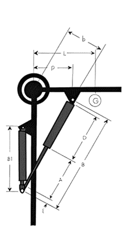
The required extension force F1 for a horizontally mounted dynamic gas spring is calculated using the formula F1 = (G × L) / (W × X) × 1.2 — sharing the same formula framework as vertical installations, but the force arm W must be re-determined based on the closed-state geometry specific to the horizontal layout.
The complete gas spring force formula F1 is presented below. All variable symbols (G, L, W, X, F1) are internationally standardized engineering notation and remain the same regardless of language:
+-----------------------------------------------------------------------+
| F1 FORCE FORMULA                                                       |
|                                                                        |
|              G × L                                                     |
|       F1 = --------- × 1.2                                             |
|              W × X                                                     |
|                                                                        |
|  G = Lid mass (kg) | L = Lever arm (mm)                                |
|  W = Force arm in closed position (mm) | X = Number of gas springs     |
+-----------------------------------------------------------------------+
How to measure each variable for horizontal mounting:
- G (Lid mass): Weigh the lid or hatch in kilograms. For a uniform lid, this is straightforward. For irregular shapes, measure the total weight — the formula accounts for the center of gravity separately via W.
- L (Lever arm): The distance from the hinge pivot to the lid's center of gravity. For a uniform rectangular lid, L is typically half the lid length. This measurement is identical in vertical and horizontal layouts.
- W (Force arm): This is the critical measurement that differs in horizontal mounting. In the closed position, measure the perpendicular distance from the hinge pivot to the gas spring's line of action. Because the gas spring is horizontal, W must be measured in the plane of the lid rather than vertically. Incorrect W values are the most common source of sizing errors.
- X (Number of gas springs): Typically X = 1 (single strut, centrally mounted) or X = 2 (one on each side). The formula divides the total torque requirement by X.
- 1.2 (Safety factor): Accounts for friction in the pivot points and temperature-related force drift between the +20 °C measurement condition and the operating range of −30 °C to +80 °C. For industrial applications with vibration or impact loads, increase to ≥1.3.
The extension force F1 is measured at 20 °C with the piston rod fully extended, based on internal test bench measurements at 400 mm/min test speed. For a deeper dive into the physics behind the formula, refer to our dedicated article on How to Calculate the Required Force for Your Gas Spring.
2.2 Worked Example: Factory Measurement Data
Let's work through a real calculation using factory-verified parameters. All figures below are taken from internal production test data — do not substitute your own values unless you have measured them directly on your application.
Given:
- G = 20 kg (lid weight)
- L = 344.3 mm (lever arm, measured from hinge to center of gravity)
- W = 74.659 mm (force arm in closed position)
- X = 2 (gas springs installed on both sides)
Step-by-step calculation:
- Calculate the torque required to hold the lid: G × L = 20 × 344.3 = 6,886 kg·mm
- Convert to force per gas spring: 6,886 / (74.659 × 2) = 6,886 / 149.318 = 46.11 kg
- Convert to Newtons (1 kg ≈ 9.81 N): 46.11 × 9.81 = 452.4 N
- Apply the safety factor: 452.4 × 1.2 = 542.33 N
Result: F1 ≈ 542 N, which should be rounded up to the nearest standard force rating — in this case, 550 N or 600 N, depending on available catalog ratings.
Why factory tolerance matters for delivery: For a nominal 700 N gas spring, the Chinese national standard GB/T 25751-2010 permits a tolerance of −25 N to +50 N (delivering 675–750 N). Through precision manufacturing, DK Gas Spring narrows this to 700–750 N as standard, with an optional narrow-tolerance band of 700–725 N available for applications requiring tight force consistency — per the dimensional and tolerance requirements of GB/T 25751-2010, verified by internal test bench measurements at 20 °C.
Verify your own calculation instantly: Use our online Gas Spring Force Calculator to input your dimensions and get an F1 recommendation in seconds.
2.3 Determining Stroke and Mounting Dimensions
Stroke is not an arbitrary choice — it is derived from the opening angle and the geometric relationship between the hinge, the gas spring mounting points, and the lid.
The gas spring stroke calculation follows these steps:
- Determine the required opening angle (e.g., 75° for a bed base, 90° for a machine hood).
- At the open position, measure the center-to-center distance between the two mounting points.
- At the closed position, measure the same distance.
- Stroke = open distance − closed distance. Both measurements must include the length of the end fittings.
Mounting dimensions must satisfy one hard constraint: the center-to-center distance in the closed position must not be less than the compressed length of the gas spring (including end fittings). Exceeding this limit can damage the internal stop or, in extreme cases, cause end cap fracture — based on internal failure analyses of over-compression incidents.
Tube/rod diameter and force range mapping:
The tube and rod diameter determines the feasible F1 range. Refer to this table when matching your calculated F1 to a standard gas spring series:
| Tube/Rod (mm) | F1 Range (N) | Typical Application |
|---|---|---|
| 8/18 | 50–400 | Light flaps, medical technology |
| 10/22 | 200–800 | Furniture flaps, fold-down beds |
| 10/28 | 400–1,200 | Machine hoods |
| 14/28 | 800–2,000 | Heavy industrial hoods |
![IMAGE PLACEHOLDER: Mounting dimension schematic — pivot point, force arm W, lever arm L, and gas spring installation position in horizontal mounting] Fig. 1: Geometric variables for F1 calculation — correct measurement of L and W determines sizing accuracy.
3. End Fittings and Mounting Brackets: Selecting M6/M8 Correctly
3.1 End Fitting Types Compared
For horizontal mounting, angle joints are compact but have limited pivot range; ball joints provide a rigid connection with a fixed pivot point; and clevis/fork heads offer the greatest freedom of movement but require more installation space — M6 is suitable for applications ≤800 N, while M8 is recommended for higher loads above 800 N.
The M6 M8 thread connection is the interface between the gas spring and your structure. Choosing the right end fitting type is as critical as the force calculation itself:
| End Fitting Type | Connection | Typical Application | Advantage / Limitation |
|---|---|---|---|
| Angle Joint | M6 / M8 | Cabinet flaps, fold-down beds | Compact; limited pivot angle |
| Ball Joint / Rod End | M6 / M8 | Machine hoods, service flaps | Robust connection; fixed pivot point |
| Clevis / Fork Head | M6 / M8 | Medical technology, industrial hoods | High freedom of movement; requires more installation space |
The ball joint rod end is the preferred choice for applications with frequent cycling, as it accommodates minor angular misalignment without transferring bending moments to the piston rod. The angle joint excels in space-constrained installations like fold-down beds, where every millimeter of clearance matters.
3.2 Mounting Brackets and Protective Accessories
The mounting bracket is not just a connector — it is the component that determines whether your gas spring operates in pure axial compression or suffers from eccentric loading. For horizontal mounting, ensure that both mounting brackets are aligned on the same axis. Even a 1–2 mm lateral offset can generate a persistent bending moment on the piston rod seal.
A protective boot (dust cover) has special value in horizontal installations. In a vertical orientation, dust and debris settle downward away from the exposed rod. In a horizontal orientation, particles can accumulate directly on the rod surface — the protective boot prevents abrasive particles from embedding in the seal lip and accelerating seal wear. All end fittings are manufactured to factory tolerances for consistent fit.
4. Hinge Protection and Lateral Force Prevention: Design-Level Safeguards
In horizontal mounting, the gas spring pivot points must ensure that the piston rod experiences only axial loading throughout the entire stroke — any sustained lateral force leads to unilateral seal wear, oil leakage, and premature failure. At the same time, correct pivot point placement reduces peak hinge loads by 30–50%.
Where side load comes from
When a gas spring is mounted horizontally, gravity acts perpendicular to the piston rod axis. If the two mounting points are not perfectly aligned on the same axis, the rod experiences a constant bending moment. This moment concentrates the contact pressure between the rod and the seal on one side — the high side of the seal wears rapidly, while the low side loses sealing contact altogether.
Installation mistakes to avoid
Based on internal failure analyses of customer complaints, the following installation errors are the most frequent causes of premature horizontal gas spring failure:
- Eccentric rod loading → unilateral seal wear → oil leakage
- Over-compression beyond the load limit → end cap fracture or tube rupture
- Misaligned mounting points → bending moment on the piston rod throughout the stroke
Hinge protection through correct pivot placement
The gas spring hinge protection principle is straightforward: position the gas spring pivot points so that the strut shares the lid's opening torque with the hinges. In a well-designed layout, the gas spring carries the majority of the static load in the open position, while the hinges only need to handle alignment — not the full weight. This reduces peak loads on hinge pins and extends the service life of the entire assembly.
Seal material selection
The choice of seal material closes the protection loop:
- NBR (Nitrile) — Standard for general-purpose applications with moderate temperatures and no chemical exposure.
- FKM (Viton) — For high-temperature environments, exposure to cleaning agents or disinfectants (e.g., medical applications), and applications requiring extended service intervals.
- PU (Polyurethane) — For extremely high wear resistance requirements, such as robotic applications exceeding 100,000 cycles.
Operating the gas spring outside the specified temperature range of −30 °C to +80 °C can cause seal hardening (low temperature) or excessive softening (high temperature), both of which compromise damping consistency.
![IMAGE PLACEHOLDER: Side load diagram — correct vs. eccentric pivot alignment in horizontal mounting] Fig. 2: Axial pivot alignment prevents lateral force and extends the service life of the sealing systems.
For more detail on the impact of installation orientation on seal life and damping, see our guide on Gas Spring Mounting Orientation: Rod Up or Rod Down?
5. Three Real-World Sizing Examples
In practice, sizing calculations differ primarily in the force-arm-to-lever-arm ratio and the required damping behavior — three examples demonstrate the full workflow for a fold-down bed, a machine hood, and a medical examination bed.
Each example follows the same three-step structure: installation situation → calculation logic → result (force class + end fitting + tube diameter).
Scenario 1: Fold-Down Bed — Horizontal Installation
| Dimension | Detail |
|---|---|
| Installation Situation | A fold-down bed (also known as an ottoman bed or storage bed) uses a gas spring mounted horizontally between the bed frame and the subframe. The flat-pack design leaves no vertical clearance for the gas strut. Bed frame weight approximately 25–35 kg, with one gas spring on each side. An ottoman bed gas spring force calculation follows the same horizontal mounting logic as any fold-down application. |
| Calculation Logic | Apply the F1 formula framework from Section 2: measure W (force arm) in the closed horizontal position. Because the hinge is near the edge of the bed frame, W is typically around 1/3 of the bed length. L ≈ W × 1.5–2 (the center of gravity is further from the hinge than the mounting point). X = 2 (bilateral installation). Safety factor 1.2. |
| Result | 10/22 mm tube/rod (F1 range 200–800 N) + M6 angle joint (compact, space-efficient) + dynamic bypass damping ensures smooth horizontal opening and closing without slamming. |
Scenario 2: Machine Hood — 45° Angled Installation
| Dimension | Detail |
|---|---|
| Installation Situation | A CNC machine cover or machine hood opens at approximately 45°. The gas spring is installed at an angle — not purely horizontal, but not vertical either. Full-stroke controlled damping is required for operator safety. |
| Calculation Logic | At 45°, W changes dynamically throughout the opening arc — a single static value is insufficient. The full-stroke force envelope must be validated (opening torque × safety factor). Safety factor ≥1.3 is recommended for industrial environments with vibration and impact loads. For complex geometries, use the force calculator to model the full opening path. |
| Result | 10/28 mm tube/rod (F1 range 400–1,200 N) + M8 ball joint / rod end (rigid, cycle-resistant connection) + operational safety in accordance with the Machinery Directive 2006/42/EC. |
Scenario 3: Medical Examination Bed — Hygienic Horizontal Installation
| Dimension | Detail |
|---|---|
| Installation Situation | A medical examination bed or hospital bed with an ultra-flat design forces horizontal gas spring mounting. The clinical environment demands resistance to disinfectant chemicals, corrosion-proof materials, and crevice-free surfaces for hygiene. A hospital bed gas spring stainless steel configuration is the standard specification for this sector. |
| Calculation Logic | Light load (mattress + bed board ≤15 kg) with tight tolerance requirements — patient comfort requires F1 tolerance narrowed to −0/+25 N (precision band). The low force range allows the use of smaller tube diameters, reducing the visual footprint. |
| Result | 8/18 mm tube/rod (F1 range 50–400 N) + M6 clevis / fork head (smooth, jerk-free motion) + material upgrade to AISI 304 / AISI 316 stainless steel — SGS salt spray test certified at 500 h+ (test report available from the manufacturer) + FKM (Viton) seals for disinfectant compatibility. |
For medical, marine, or any hygiene-critical application, explore our Stainless Steel Gas Springs for maritime and hygienic environments.
Once you have identified the right force class and tube diameter for your application, browse the full range of configurations in our Compression Gas Springs – Product Overview.
6. Procurement Acceptance: What to Check in the Technical Specification
Regardless of how precisely you have sized the gas spring, technical buyers should verify at least four hard metrics upon receiving supplier quotations and samples: cycle life (≥30,000 cycles without leakage, per GB/T 25751-2010), F1 force tolerance (standard −25/+50 N, precision −0/+25 N), corrosion resistance rating (stainless steel SGS salt spray 500 h+), and CAD data delivery completeness.
Acceptance checklist
| Acceptance Criterion | Minimum Requirement | Test Basis |
|---|---|---|
| Cycle Life | ≥ 30,000 cycles without leakage; up to 50,000 cycles (< 5% force loss) | GB/T 25751-2010; internal test bench measurements with full-stroke compression |
| Force Tolerance (F1) | −25 N / +50 N (standard); −0 N / +25 N (precision) | Internal test bench measurement at 20 °C |
| Corrosion Resistance | ≥ 500 h salt spray test (stainless steel) | SGS test report (report number available from the manufacturer) |
| Temperature Range | −30 °C to +80 °C | Factory specification |
The gas spring force specification should always be requested as part of the quotation package — a reputable OEM manufacturer provides this alongside CAD model download files (STEP or IGES format) so that you can integrate the gas spring directly into your assembly model.
Force values above are measured at 400 mm/min test speed and 20 °C ambient temperature, per GB/T 25751-2010 and GB/T 25750-2010. For applications requiring extended cycle life — such as robotic automation reaching 100,000 cycles — specify FKM (Viton) seals at the RFQ stage. Stainless steel variants (AISI 304 / AISI 316) should be verified with an SGS salt spray certificate referencing a test duration of ≥500 hours; test report numbers are available from the manufacturer upon request.
Need CAD data or a precise force calculation for your horizontal mounting?
Our application engineers calculate F1 force and stroke for your specific installation situation and provide the matching 3D CAD models and end fittings.