
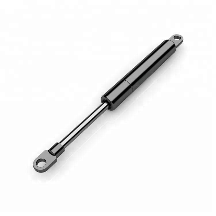
What Is a Dynamic Gas Spring? How It Works and Key Advantages Explained
What Is a Dynamic Gas Spring? How It Works and Key Advantages Explained
Across modern mechanical engineering, medical technology, and the furniture industry, design engineers face a recurring challenge: covers, flaps, or heavy assemblies must be smoothly damped and moved in a controlled manner — often within extremely constrained installation spaces. Conventional hydraulic gas springs quickly reach their physical limits when the mounting orientation deviates from the vertical.
A dynamic gas spring provides an engineered solution to this problem. By incorporating a cylinder inner profile with defined bypass geometry, it enables largely position-independent mounting and precisely controllable damping characteristics across the entire stroke.
1. The Problem with Conventional Hydraulic Gas Springs: Mounting Orientation and End-of-Stroke Damping
Conventional hydraulic gas springs require the piston rod to be oriented downward, as the damping oil must flow to the cylinder base under gravity in order to deliver damping action at the end of the stroke.
In a classic hydraulic configuration, the cylinder contains a precisely metered volume of oil in addition to compressed nitrogen gas. As the piston rod extends, the piston travels through the gas chamber with virtually no resistance. Only when the piston plunges into the oil volume at the end of the stroke does the higher viscosity of the oil produce the intended end-position damping.
+-----------------------------------------------------------------------+
| HYDRAULIC DAMPING (Position-Dependent)                                |
| Cylinder Chamber (Gas) ----------> Oil Layer (Cylinder Base)           |
| [Piston travels through gas] ---> [Piston plunges into oil -> Damping]|
| *Mandatory requirement: Piston rod pointing downward!                 |
+-----------------------------------------------------------------------+
This operating principle imposes a strict mounting orientation:
- Restricted Installation: The piston rod must point downward when installed. If the gas spring is mounted horizontally or with the piston rod facing upward, the oil collects at the wrong end of the cylinder.
- Consequence of Incorrect Installation: End-position damping fails completely. The assembly slams into its end stop uncontrolled, subjecting hinges to high mechanical peak loads. Additionally, the risk of internal NBR or FKM seal wear increases due to uneven lubrication.
In compact installation spaces — such as flat-opening flaps, fold-down beds, or medical adjustment mechanisms — vertical orientation is often technically infeasible.
2. Operating Principle: How Does a Dynamic Gas Spring with Longitudinal Groove Work?
A dynamic gas spring uses a precision-machined longitudinal groove (bypass) in the cylinder inner wall, through which nitrogen gas flows past the piston in a controlled manner throughout the entire stroke, generating position-independent damping.
2.1 Flow Restriction via the Cylinder Profile (Longitudinal Groove / Bypass)
Unlike hydraulic gas springs, damping in the dynamic variant is not based on plunging into an oil bed, but on the purposeful flow of compressed gas past the piston.
- Precision Groove in the Cylinder Wall: A fine groove profile is cut or formed into the inner wall of the pressure tube.
- Gas Flow Instead of Valve Orifice: As the piston rod extends, gas flows through this lateral bypass past the piston from one side to the other.
- Controlled Velocity Profile: The geometry and depth of the longitudinal groove taper toward the end of the stroke. This progressively reduces the flow cross-section for the gas. The extension speed is precisely reduced along the travel path — entirely independently of where liquid media are located within the cylinder.
2.2 The Decisive Advantage: Position-Independent Mounting Orientation
Since the damping effect is primarily determined by the mechanical groove geometry and the gas flow, dependence on gravity is eliminated.
- Free Mounting Angle (0° to 360°): Dynamic gas springs can be installed in horizontal orientations or with the piston rod pointing upward.
- Jerk-Free Motion Sequences: The transition into the damping phase is stepless, preventing abrupt shocks and protecting adjacent structural components.
3. Dynamic vs. Hydraulic Damping: A Direct Comparison
While hydraulic damping depends on the oil level at the cylinder base and only works in a position-dependent manner, dynamic damping offers position-independent, precisely definable motion control across the entire stroke profile.
The following overview summarizes the key technical differences for design engineering practice:
| Technical Property / Parameter | Hydraulic Gas Spring | Dynamic Gas Spring (Longitudinal Groove) |
|---|---|---|
| Primary Damping Medium | Hydraulic oil at cylinder base | Compressed nitrogen gas via bypass |
| Mounting Position | Position-dependent (piston rod downward) | Position-independent (0°–360°, e.g. horizontal) |
| Damping Curve | Localized at stroke end (plunging into oil) | Continuous / Definable via groove profile |
| Side Load & Wear Protection | Higher risk with misalignment | Balanced pressure distribution at piston |
| Typical Applications | Standard vertical hoods, vehicle tailgates | Horizontally constrained spaces, medical technology |
For detailed comparisons and selection criteria between these systems, see also our technical article on hydraulic damping compared to dynamic designs.
4. Technical Parameters, Sizing, and Quality Standards
Precise sizing of a dynamic gas spring is based on calculating the required extension force ( value in Newtons), selecting suitable end fittings, and adhering to tight manufacturing tolerances.
+-----------------------------------------------------------------------+
| F1 FORCE FORMULA FOR CALCULATION                                      |
|                                                                       |
|              G x L                                                    |
|       F1 = --------- x 1.2                                            |
|              W x X                                                    |
|                                                                       |
|  G = Mass (kg) | L = Lever Arm (mm) | W = Force Arm (mm) | X = Qty.  |
+-----------------------------------------------------------------------+
4.1 Calculating the Extension Force ()
The required extension force is measured at with the piston rod fully extended. For theoretical preliminary sizing, the following field-proven formula applies:
- : Weight of the flap / mass to be lifted in kg
- : Distance from pivot point to center of gravity in mm
- : Effective force arm of the gas spring in the closed position in mm
- : Number of gas springs used in parallel
- : Safety factor for friction and temperature deviations
4.2 Manufacturing Tolerances and Pressure Ranges
In series production machinery, adherence to tight force tolerances is essential:
- Standard Tolerances: Per industrial testing standards, the deviation for a defined nominal force (e.g. ) typically falls within to .
- Precision Manufacturing: For sensitive applications, the tolerance band can be narrowed to – through production process control.
Detailed information on correct mathematical sizing can be found in the guide for horizontal mounting and precise F1 force calculation.
4.3 Tube Specifications, Seals, and Service Life
Dynamic gas springs are manufactured in various diameter ratios to accommodate different extension forces ( from to ):
| Size (Rod/Tube) | Typical Force | Recommended Application |
|---|---|---|
| 8/18 mm | 50 – 400 N | Lightweight flaps, medical technology |
| 10/22 mm | 200 – 800 N | Furniture flaps, fold-down beds |
| 10/28 mm | 400 – 1,200 N | Machine hoods, service access panels |
| 14/28 mm | 800 – 2,000 N | Heavy industrial hoods |
- Operating Temperature: Standard configurations reliably cover the temperature range from to .
- Sealing Systems & Endurance: In addition to standard NBR seals, fluorocarbon rubber (FKM/Viton) or PU seals are available for elevated requirements. Based on internal test-stand measurements, standard models achieve at least cycles without leakage per GB/T 25751-2010; specially configured systems pass endurance tests of up to cycles with less than gas pressure loss.
- Materials & Corrosion Protection: Cylinders are typically made of carbon steel with a black protective coating. For maritime or hygienically demanding environments, stainless steel versions (AISI 304 / AISI 316) are available, which demonstrably remain corrosion-resistant for over in the SGS salt spray test. Further details can be found on our stainless steel gas springs page.
- End Fittings: M6 and M8 threaded connections enable attachment of angle joints, rod eyes, or fork heads, optionally supplemented by protective boots against dust and debris.
5. Typical Industrial Applications
Dynamic gas springs are preferentially used in applications where space constraints demand horizontal mounting positions or where smooth, defined end-position damping without impact shocks is essential.
Furniture Industry & Folding Mechanisms
In modern furniture construction (e.g. ottoman storage beds or high-end cabinet flaps), the dynamic gas spring prevents hard slamming. This results in noticeably reduced hinge stress and extends the service life of the entire assembly.
Medical Technology & Care Equipment
For adjustable treatment chairs, patient beds, or mobile diagnostic devices, stepless and low-noise adjustment sequences are safety and comfort criteria. The horizontal mounting capability enables flat underframe designs.
Mechanical Engineering & Automation
Protective hoods on machine tools or service access panels on enclosures often require inclined or horizontal pivot points. Dynamic gas springs ensure safe hold-open and controlled manual closing without excessive hand force.
Conclusion & Technical Consultation
The dynamic gas spring significantly expands the design envelope in modern B2B mechanical engineering. Through the longitudinal groove in the cylinder bore, it offers position-independent mounting combined with a steplessly tunable damping profile.
For a side-by-side evaluation of whether the switch from hydraulic to dynamic damping is justified in your specific case — including cost, damping curve, and mounting orientation trade-offs — see our dedicated comparison: Dynamic vs. Hydraulic Damping in Gas Springs: When Is the Switch Worth It?.
Need CAD data or a custom force calculation for your design?
Our application engineers support you in the precise sizing of dynamic gas springs (determination of force, stroke curve, and M6/M8 connection components).