
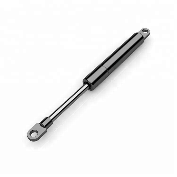
Dynamic vs. Hydraulic Damping in Gas Springs: When Is the Switch Worth It?
Dynamic vs. Hydraulic Damping in Gas Springs: When Is the Switch Worth It?
In engineering practice, designers are increasingly confronted with a decision that was rarely discussed just a few years ago: hydraulic or dynamic damping in a gas spring? The trigger is almost always the same — a mounting situation in which the classic rule "piston rod must point downward" cannot be observed, and the gas spring damping fails completely in horizontal mounting.
More and more engineers are replacing hydraulic gas springs with dynamic variants because dynamic damping operates independently of mounting orientation and delivers a stepless damping curve that can be defined across the entire stroke — without the "piston rod down" restriction. But the switch comes at a cost: manufacturing a precision longitudinal groove in the cylinder inner wall is more complex than a conventional hydraulic setup.
This technical article provides a detailed comparison of both systems, a robust decision matrix for design engineers, and three practical scenarios where switching to a dynamic gas spring demonstrably pays off. (We have already described the physical fundamentals of longitudinal groove technology in detail in our article on Dynamic Gas Spring Basics.)
1. Why More Engineers Are Switching to Dynamic Damping
The decisive driver behind this shift is the growing space constraints in modern designs. Flat construction methods in fold-down beds, compact machine enclosures, and medical examination couches with minimal installation height simply leave no room for the vertical orientation that a hydraulic gas spring absolutely requires.
Three factors are intensifying this trend:
- Miniaturization in equipment design: Machine guards and service flaps are becoming increasingly flat. A 45° inclined or horizontal mounting orientation cannot be reliably damped with hydraulic systems — the oil distributes uncontrollably within the cylinder, and end-position damping engages unpredictably or not at all.
- Rising comfort and safety requirements: In medical technology and high-end furniture, users expect silent, jerk-free movement across the entire travel range. A damping system that only acts on the final 30% of the stroke no longer meets these demands.
- Hinge relief as a cost factor: Undamped slamming hoods or flaps generate high peak loads on hinges and mounting points. The consequences are premature material fatigue, service call-outs, and warranty claims — costs that do not appear in a simple unit-price comparison of the gas spring, but are significant in a lifecycle cost analysis.
The central question for the design engineer is therefore no longer just "What force rating do I need?", but increasingly: "When does the switch from hydraulic to dynamic damping pay off — and when is the simpler solution sufficient?"
2. Technical Comparison: Dynamic vs. Hydraulic Damping in Detail
The key difference lies in the damping medium and flow control: Hydraulic damping only generates its effect when the piston plunges into the oil volume at the cylinder base (position-dependent), while dynamic damping allows the nitrogen gas to flow past the piston in a controlled manner via a longitudinal groove in the cylinder wall (position-independent).
2.1 Comparison Table: 6 Technical Dimensions
The following comparison shows the differences between the two systems across the characteristics relevant to engineering practice:
| Technical Feature | Hydraulic Gas Spring | Dynamic Gas Spring (Longitudinal Groove) |
|---|---|---|
| Damping Principle | Piston plunges into oil volume at stroke end | Gas flows past piston in controlled manner via bypass groove |
| Mounting Orientation | Restricted: piston rod must point downward | Free: 0°–360°, including horizontal or piston rod upward |
| Damping Curve | Localized at stroke end (final ~30% of stroke) | Continuous across entire stroke; damping curve definable via groove geometry |
| Hinge Loading | Higher peak load due to abrupt deceleration in oil | Reduced peak load through uniform deceleration across entire stroke |
| Manufacturing Complexity | Simple cylinder construction; standard hydraulic oil | Precision groove required in cylinder inner wall; tighter manufacturing tolerances |
| Relative System Cost | Base price level (economical for standard vertical applications) | Slightly higher unit cost, offset by reduced hinge loading and longer system service life |
The decisive row in practice is the last one: the higher unit cost of a dynamic gas spring is always amortized when the uniform damping curve prevents costly consequential damage to hinges, frames, or seals. For a purely vertical application without special damping curve requirements, however, the hydraulic version remains the more economical choice.
2.2 Damping Curve: Direct Comparison
The different operating principles produce fundamentally different damping characteristics:
-
Hydraulic Damping — localized deceleration: During the first 60–70% of the extension stroke, the piston moves through the gas volume with virtually no resistance. Only when the piston plunges into the oil at the cylinder base does the damping effect engage abruptly. The result is a damping curve with a steep velocity drop at the stroke end — functionally adequate for many standard applications, but with increased moment loading on the connection points.
-
Dynamic Damping — continuous deceleration: The longitudinal groove machined into the cylinder wall tapers in a controlled manner toward the stroke end. This progressively reduces the flow cross-section for the gas across the entire stroke — regardless of whether the gas spring is mounted horizontally, vertically, or at an angle. The extension velocity decreases uniformly. The result is a smooth, predictable, and above all reproducible motion sequence.
![IMAGE PLACEHOLDER: Damping Curve Comparison Diagram — Hydraulic (localized) vs. Dynamic (continuous)]
Fig. 1: Schematic comparison of velocity profile over stroke — hydraulic damping (localized, position-dependent) vs. dynamic damping (continuous, position-independent).
3. Structural Difference: Bore vs. Longitudinal Groove in the Cylinder Profile
In hydraulic damping, there is no structured flow control in the cylinder wall — the piston moves freely through the gas until it plunges into the oil. In the dynamic version, by contrast, a precision longitudinal groove (bypass) is machined into the cylinder inner wall, whose cross-sectional geometry decreases toward the stroke end, thereby reducing the extension velocity in a controlled manner.
The core structural difference can be seen in the two cylinder cross-sections:
Hydraulic Version:                 Dynamic Version:
┌─────────────────────┐            ┌─────────────────────┐
│   Cylinder Wall      │            │   Cylinder Wall      │
│  ┌───────────────┐   │            │  ╔═══════════════╗   │ ← Longitudinal
│  │    Piston     │   │            │  ║   Piston     ║   │   Groove (Bypass
│  │   with Bore   │   │            │  ║              ║   │   in Cylinder Wall)
│  │ (Gas Equaliz.) │   │            │  ║              ║   │
│  └───────────────┘   │            │  ╚═══════════════╝   │
│        Oil           │            │        Gas           │
└─────────────────────┘            └─────────────────────┘
In the hydraulic version, the piston has a small central bore — however, this serves exclusively for pressure equalization between the upper and lower sides of the piston, not for controlled damping. Damping only occurs through the higher viscosity of the oil into which the piston plunges at the stroke end.
In the dynamic version (gas spring with longitudinal groove), the damping characteristic is "programmed" directly into the cylinder wall. The depth and width of the groove define how much gas can flow past the piston per unit of time. A tapering groove geometry means: the further the piston extends, the narrower the bypass channel becomes — the velocity decreases steadily.
Manufacturing this groove requires higher precision in cylinder machining and is subject to tighter tolerances, monitored in accordance with GB/T 25751-2010 (broadly equivalent to DIN EN ISO 13214). Depending on requirements, standard NBR seals or optional FKM seals (Viton) for high-load applications are used for the sealing systems.
4. Decision Matrix: When Dynamic, When Hydraulic?
A dynamic gas spring is always the right choice when the mounting orientation cannot be realized vertically with the piston rod downward, when a defined damping curve across the entire stroke is required, or when adjacent components (hinges, frames) must be protected against peak loads.
4.1 Scenarios: Dynamic Damping Is the Better Choice
| Application Scenario | Technical Rationale |
|---|---|
| Horizontal or piston-rod-up mounting | Hydraulic oil collects at the wrong end of the cylinder → damping fails |
| Flat flaps / fold-down beds / medical couches | Installation space does not permit vertical gas spring alignment |
| Machine hoods with angled linkage | Mixed mounting orientations; oil position in cylinder not constant |
| High-comfort applications | Stepless damping curve = no jerking, no noise |
| Limited hinge load capacity | Uniform deceleration reduces peak load at connection points |
4.2 Scenarios: Hydraulic Damping Is Sufficient
| Application Scenario | Technical Rationale |
|---|---|
| Standard vertical mounting (piston rod down) | Oil reliably collects at cylinder base under gravity |
| End-position damping only, no stroke-profile requirements | Localized damping at stroke end meets the requirement |
| Cost-sensitive high-volume production with vertical orientation | Simpler cylinder construction = more economical at high volumes |
4.3 Decision Tree for Design Engineers
The following decision logic provides quick guidance during the design phase:
1. Is the piston rod oriented downward in the installed state?
→ NO: Dynamic gas spring required. (Oil collects at the wrong end of the cylinder in horizontal or piston-rod-up mounting — damping fails.)
→ YES: Continue to Question 2.
2. Is a uniform damping curve required across the entire stroke?
→ YES: Dynamic gas spring recommended. (Only the bypass groove delivers continuous deceleration across the full stroke.)
→ NO: Continue to Question 3.
3. Are adjacent hinges or frame components sensitive to peak loads?
→ YES: Dynamic gas spring recommended. (Hinge relief through uniform deceleration prevents premature wear.)
→ NO: Hydraulic gas spring sufficient.
![IMAGE PLACEHOLDER: Decision Tree Diagram — Dynamic vs. Hydraulic Damping — Flowchart for Design Engineers]
Fig. 2: Decision logic for selecting the damping system — three check questions for rapid identification of the optimal gas spring configuration.
Once you have identified the right system, our detailed Compression Gas Springs overview will assist with further specification. For precise calculation of the required force rating, we recommend the Gas Spring Force Calculator.
5. Practical Examples: Where Switching to Dynamic Damping Pays Off
Switching to dynamic damping pays off wherever the avoided costs of hinge breakage, premature seal wear, or service call-outs exceed the higher unit cost of the dynamic gas spring — typically in confined installation spaces, mixed mounting orientations, and high quality requirements.
Scene 1: Fold-Down Bed with Horizontal Gas Spring Mounting
A manufacturer of fold-down beds is designing a new model with minimal installation depth. The gas spring must be mounted horizontally between the bed frame and the subframe — vertical orientation is impossible due to space constraints.
- Problem: In the hydraulic version, the damping oil distributes uncontrollably along the horizontally positioned cylinder wall. When closing the bed, the piston does not reliably encounter the oil volume — damping fails. The frame slams hard against the subframe; the hinges are subjected to a peak load with every closing cycle. After just a few hundred cycles, the first hinge loosening occurs; customers complain about the loud impact noise. The same problem occurs in ottoman beds where gas strut damping must be installed horizontally — here too, the hydraulic version is structurally overwhelmed.
- Solution: Switch to a dynamic gas spring with a bypass groove. Since damping is controlled via gas flow rather than oil position, it functions independently of mounting orientation.
- Result: The frame closes smoothly and silently across the entire stroke. Hinge loading drops to a level that enables the mechanism to achieve its specified service life without premature failures. Impact-related complaints are eliminated.
Scene 2: CNC Machine Guard with Angled Linkage
A machine builder is equipping a CNC machine tool with a protective guard that opens at a 45° angle. The gas spring is mounted at an angled linkage point.
- Problem: In the hydraulic version, the 45° inclined position results in a constantly shifting oil position within the cylinder. Depending on whether the machine is cold in the morning or warm after several hours of operation, the oil viscosity — and thus the damping effect — varies. This is a safety-critical factor, as the guard could slam shut uncontrollably with insufficient damping. This conflicts with the requirements of the Machinery Directive 2006/42/EC.
- Solution: Use of a dynamic gas spring with position-independent mounting. Damping is purely gas-based via the longitudinal groove — temperature-related oil viscosity fluctuations play no role.
- Result: Reproducible, safe closing sequence under all operating conditions. The guard closes in a controlled manner and meets mechanical engineering safety requirements. Hinge loading is distributed evenly across the entire swivel range thanks to the continuous damping curve.
Scene 3: Medical Examination Bed
A manufacturer of medical examination couches and hospital beds is developing a height-adjustable model in a flat design. For hospital beds with integrated gas spring damping, the mounting situation is frequently identical: the installation height of the subframe does not permit vertical alignment. The backrest is locked in multiple positions via a gas spring.
- Problem: The extremely flat construction of the subframe does not allow vertical mounting of the gas spring — the piston rod must be mounted horizontally. A hydraulic gas spring would not provide reliable end-position damping in this orientation. At the same time, the hospital environment imposes high demands on hygiene and corrosion resistance.
- Solution: Dynamic gas spring in horizontal mounting orientation, optionally manufactured in AISI 304 stainless steel for enhanced corrosion resistance. Depending on disinfectant exposure, the sealing systems can be upgraded from standard NBR to FKM (Viton). The operating temperature range of −30 °C to +80 °C reliably covers all clinical application scenarios.
- Result: Stepless, low-noise backrest adjustment — a decisive comfort feature for patients and nursing staff. For further details on corrosion-resistant versions, see our page on Stainless Steel Gas Springs for maritime and hygienic environments.
6. Quality and Service Life: What to Look for in Procurement
Regardless of the damping system chosen, design engineers and technical buyers should focus on documented test data — not marketing claims — when evaluating a gas spring OEM supplier. The following four inspection criteria form a reliable basis for a gas spring quality comparison:
| Inspection Criterion | Minimum Requirement | Test Basis |
|---|---|---|
| Cycle Life | ≥ 30,000 cycles without leakage (standard); up to 50,000 cycles with < 5% force loss (extended specification) | GB/T 25751-2010 / broadly equivalent to DIN EN ISO 13214; based on internal test-stand measurements with full-stroke compression |
| Force Tolerance (F1) | −25 N / +50 N (standard); −0 N / +25 N (precision manufacturing) | Internal test-stand measurement at 20 °C with piston rod extended |
| Corrosion Resistance | ≥ 500 h salt spray test without functional failure (stainless steel version) | SGS salt spray test per DIN EN ISO 9227 NSS, ≥ 500 h without functional failure |
| Temperature Range | −30 °C to +80 °C | Factory specification; based on sealing system (NBR standard / FKM optional) |
Stating cycle counts without specifying the test basis (e.g., "50,000 cycles" without reference to the permissible force loss) is worthless in a B2B context. As a technical buyer, insist on your supplier's F1 tolerance documentation — it is the most direct indicator of manufacturing process capability. For high-load applications and long service intervals, optional FKM seals (Viton) are available, offering higher thermal and chemical resistance than standard NBR.
Conclusion: The Switch Is a Question of Mounting Situation — Not Technology
Dynamic and hydraulic gas springs are not competing technologies, but complementary tools in the design engineer's toolkit. Hydraulic damping remains the more economical choice for all applications where the piston rod can be mounted downward and localized end-position damping is sufficient. Dynamic damping is always the right decision when the mounting orientation deviates from the vertical, when the damping curve must be defined across the entire stroke, or when adjacent components must be protected against peak loads.
The question posed at the outset — "When is the switch worth it?" — can thus be reduced to a precise engineering principle: It is not the technology that decides — but the mounting situation, the required damping curve, and the service life expectations for the overall system.
Need a technical decision guide for your next design project?
Our application engineers analyze your mounting situation and recommend the economically and technically optimal damping system — including CAD data and force calculations.