Gas Springs: Complete Guide to Types, Functions, Applications & How to Choose the Right One
Gas Springs: Complete Guide to Types, Functions, Applications & How to Choose the Right One
If you’ve ever wondered how heavy hatches lift effortlessly, hospital beds adjust smoothly, or industrial machinery handles heavy loads with precision, chances are a gas spring or gas strut is working behind the scenes. These unsung heroes of motion control power countless devices across industries, yet their complexity often leaves users with questions: What exactly is a gas spring? Which type fits my project? How do I calculate the exact force needed? What material should I specify?
At DK Gas Spring, we’ve engineered this truly complete guide to answer every question — from basic principles to advanced calculations with angle compensation, material selection guides, and installation rules. Whether you’re a design engineer, a procurement manager, or a maintenance technician, this hands‑on resource will give you the confidence to select, install, and maintain the ideal pneumatic solution. Let’s dive in.
Authored by Bob Reynolds, Senior Mechanical Engineer at DK Gas Spring, with over 10 years of experience in motion control and gas spring design.
What Is a Gas Spring? Definition & Working Principle
A gas spring (also known as a gas strut or gas lift) is a mechanical device that uses compressed gas (typically nitrogen) contained in a cylinder to generate a force. This force enables smooth, controlled motion — whether lifting, lowering, supporting, or damping movement.
Watch it in action – this 30‑second 3D animation makes the internal process crystal clear:
How Do Gas Springs Work?
The core structure includes:
- A cylinder filled with compressed nitrogen gas.
- A piston with small orifices that separates the gas chamber from a smaller oil chamber (in damped models).
- A rod connected to the piston, extending outside the cylinder.
When force is applied to the rod (e.g., pushing or pulling), the piston moves, compressing the gas. The compressed gas exerts an opposing force, creating controlled motion. In dampers or shock absorbers, oil flows through the orifices to slow motion, reducing impact and vibration.
 Cross‑section diagram: 1 – Rod, 2 – Seal, 3 – Piston with orifices, 4 – Gas chamber (nitrogen), 5 – Oil chamber (damping medium)
Types of Gas Springs: A Detailed Comparison
Gas springs vary by design to suit specific applications. Below is a breakdown of the most common types, their features, and ideal uses:
| Type | Key Features | Primary Applications |
|---|---|---|
| Compression Gas Spring | Most common type; generates force when the rod is pushed into the cylinder. | Car hoods, office chairs, cabinet doors, industrial machinery hatches. |
| Tension Gas Spring | Works in reverse — exerts force when the rod is pulled out of the cylinder. | Canopies, fold‑down beds, door closers, marine equipment. |
| Locking Gas Spring | Features a valve to lock the rod in any position, maintaining force without external input. | Medical beds, adjustable workbenches, theatrical equipment, RV awnings. |
| Adjustable Gas Spring | Allows pressure adjustment via a valve, altering force output as needed. | Furniture (sofas, tables), fitness equipment, custom industrial tools. |
| Pneumatic Damper | Focuses on damping motion (not just lifting) using oil‑gas combination. | Automotive suspension, heavy machinery, robotics, conveyor systems. |
Table 1: Comparison of Gas Spring Types
Specialized Variants:
- Industrial Damping Solutions: Designed for high‑load, high‑cycle applications (e.g., 200,000 times lifecycle).
- Pneumatic Cylinders/Actuators: Integrate with pneumatic systems for automated motion in manufacturing lines.
- Energy Absorbers: Optimized to dissipate kinetic energy, protecting equipment from sudden impacts.
Material & Surface Treatment Options
In B2B procurement, material selection often comes before force calculation. The environment dictates the material, and the material dictates the price. Choose the right base material and coating to match your application’s demands.
| Material Grade | Surface Treatment | Corrosion Resistance | Typical Applications |
|---|---|---|---|
| Standard Carbon Steel | Black electrophoretic coating (E‑coat) or painted | Moderate — indoor use only | Automotive hoods, office chairs, indoor machinery guards, general furniture |
| 304 Stainless Steel (V2A) | Natural or polished finish | High — suitable for frequent washdowns and outdoor use | Medical equipment, food processing lines, cleanrooms, outdoor kiosks, swimming pool lifts |
| 316L Stainless Steel (V4A) | Electro‑polished (optional) | Extreme — designed for marine and chemical exposure | Yacht hatches, offshore oil rig platforms, coastal architecture, fertilizer plants, pharmaceutical wash zones |
Table 2: Material Selection Guide
Pro tip: If your gas spring will be exposed to salt spray, chlorinated water, or aggressive cleaning chemicals, always specify 316L stainless steel. The price difference is small compared to the cost of premature failure and on‑site replacement downtime.
Key Functions & Advantages of Gas Springs
Gas springs offer unique benefits that make them indispensable in modern engineering:
- Efficient Force Generation: Lift heavy objects (up to thousands of pounds) with minimal manual effort — ideal for ergonomic designs.
- Smooth, Controlled Motion: Eliminate jerky movements, reducing wear on machinery and improving user safety.
- Damping & Shock Absorption: Reduce vibration and impact, extending equipment lifespan (critical in automotive and industrial settings).
- Compact Design: Deliver high force in a small footprint, saving space in tight installations (e.g., medical devices).
- Low Maintenance: No external power source needed; nitrogen gas is inert, preventing corrosion and ensuring long life (typically 50,000+ cycles).
Applications: Where Gas Springs Shine Across Industries
Gas springs are versatile, with applications spanning nearly every sector. Here are key use cases, brought to life with real‑world visuals:

Automotive
Hoods, trunks, and tailgates (support and easy access). Suspension systems (pneumatic suspension for smooth rides). Seat adjustment (height and recline control).

Furniture & Interior
Office chairs (height adjustment via gas lifts). Cabinet doors and fold‑down tables (soft closing). Beds (adjustable head/foot sections with locking gas springs).

Industrial Manufacturing
Watch the damped motion of an industrial hatch. Machinery hatches and access panels (safe lifting). Conveyor systems (pneumatic dampers for speed control). Robotics (precision motion with pneumatic actuators).

Medical & Healthcare
Hospital beds (adjustable positions for patient comfort). Wheelchair lifts (smooth, safe elevation). Medical carts (stable movement with shock absorption).

Aerospace & Marine
Aircraft cabin doors and storage compartments. Boat hatches and foldable decks (corrosion‑resistant designs).
How to Choose the Right Gas Spring: A Step-by-Step Guide
Selecting the correct gas spring ensures optimal performance and safety. Follow these six steps, now with the exact calculation and real‑world angle considerations every engineer needs.
-
Define the Application: Determine if you need lifting, lowering, supporting, or damping.
-
Calculate the Exact Force Required — We won’t stop short. The force needed depends on the weight of the lid, its center of gravity, and the mounting geometry. The fundamental equation stems from the lever principle:
Ideal scenario (simplified): F = (W × L) / d
- F = Required gas spring force
- W = Weight of the lid/object (in Newtons — multiply kg by 9.8)
- L = Distance from hinge to the center of gravity (meters)
- d = Perpendicular distance from hinge to the gas spring mounting point (meters)
Note: This simplified formula assumes the gas spring force is perfectly perpendicular to the lid. In reality, the gas spring is mounted at an angle, and the effective lever arm changes throughout the opening arc.
Real‑world application (with angle compensation): In practice, the gas spring exerts force at an angle () to the lid. The effective perpendicular distance becomes . Therefore, the required spring force at any given point is calculated as:
Where is the angle between the gas spring’s axis and the lid (or the line connecting the mounting point to the hinge). This angle changes as the lid opens, which is why the highest required force usually occurs at the fully closed position where is smallest. For complex motion profiles tracking this angle through the entire opening arc, use our digital tool below.
Worked example (simplified) For this introductory engineering scenario, we assume the hatch is at a horizontal position where the gas spring acts perfectly perpendicular to the panel (), allowing us to use the simplified baseline formula: Let’s calculate for a machine cover weighing 20 kg, with its center of gravity 0.5 m from the hinge, and a mounting point 0.1 m from the hinge.
W = 20 kg × 9.8 = 196 N
F = (196 N × 0.5 m) / 0.1 m = 980 N
Apply a 20% safety factor: 980 N × 1.2 ≈ 1176 N You should select a gas spring with a nominal force around 1200 N.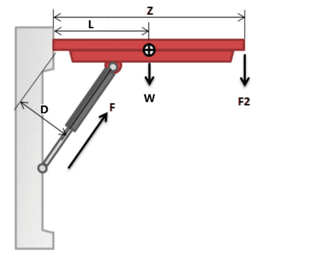
-
Determine Stroke Length: Measure the distance the rod needs to extend/retract.
Understand Progressivity (K-Factor): Note that a gas spring's force profile is not perfectly linear. Due to internal volume displacement as the rod enters the cylinder, the force required when fully compressed () is typically 20% to 40% higher than the initial extended force (). When finalizing your design, ensure that all hinges, brackets, and structural framing are rated to handle this peak mechanical load at the fully closed position.
-
Consider Environmental Factors: Refer back to the Material & Surface Treatment Options table above to select the correct body and rod material for your operating temperature, humidity, and chemical exposure.
-
Choose the Type: Opt for adjustable gas springs for variable loads, locking types for fixed positions, or dampers for vibration control.
-
Verify with Our Interactive Tool — Now put your numbers to the test. Our digital selection tool handles the full trigonometric tracking of through the entire range of motion.
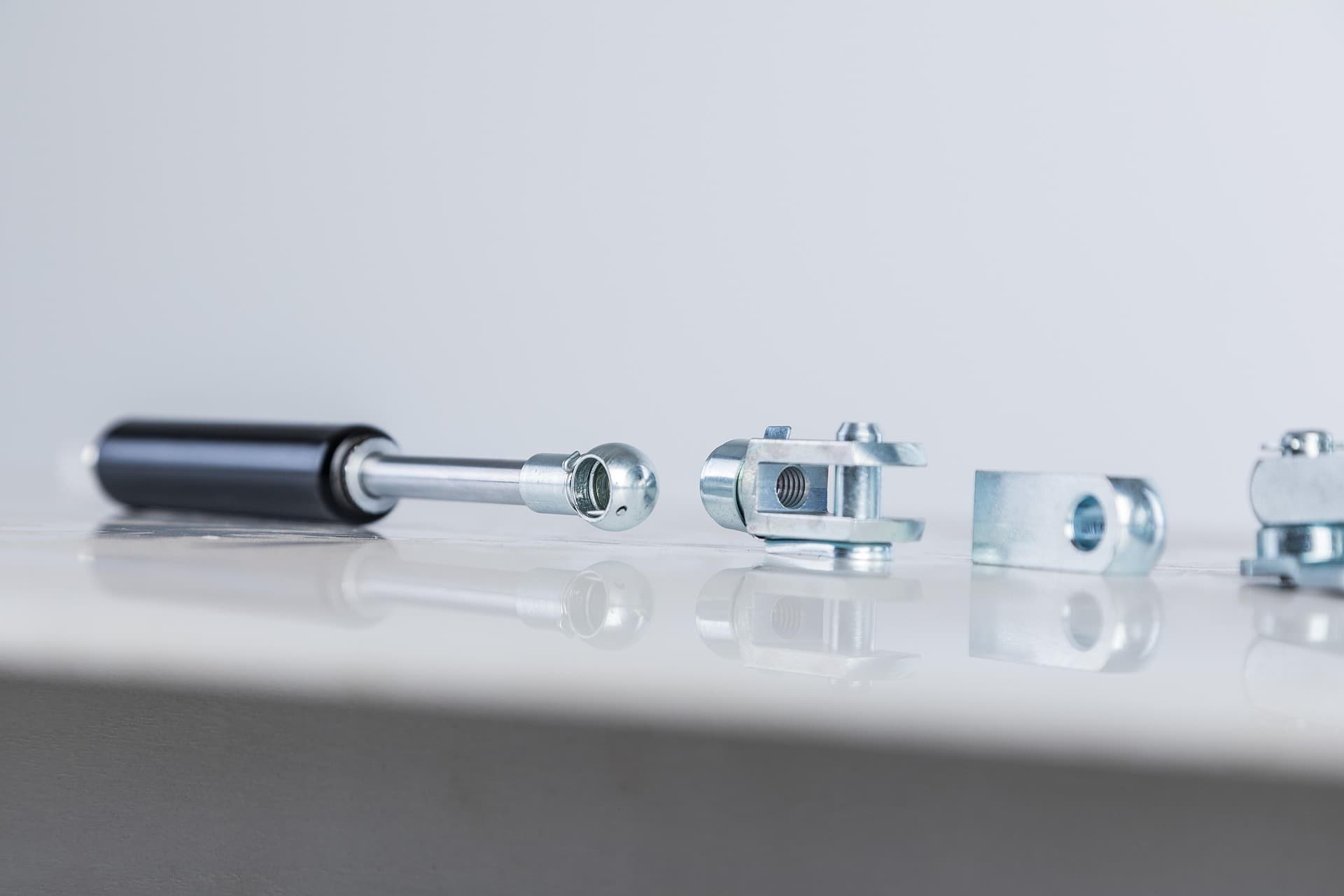
End Fitting Types & Their Applications
Before finalizing your design, you must specify the end fittings. The right connector ensures proper force transmission and allows the necessary freedom of movement.
| End Fitting Type | Key Characteristic | Best Suited For |
|---|---|---|
| Ball Joint (Ball & Socket) | Allows angular misalignment up to ±15°; quick snap‑on assembly. | Light to medium‑duty applications like automotive hoods, access panels, and furniture where perfect linear alignment isn’t guaranteed. |
| Clevis Fork (U‑Bracket) | Provides a rigid, high‑strength connection using a through‑bolt or pin; handles push and pull forces with zero play. | Heavy‑duty industrial hatches, machine guards, and applications with high transverse loads or where precise pivoting is critical. |
| Eyelet (Fixed Eye) | A single, fully enclosed ring; simple and strong but requires disassembly for mounting. | Tension springs, linkage pivots, and situations where the spring must not accidentally disconnect. |
| 90° Swivel Bracket | Designed for side‑mounting where space is constrained. | Cabinet |